Every well-equipped wood shop has a dust collection system, with blast gates at every tool to direct the suction power where you need it. If these gates are hard to reach they can be real pain to operate. [Cosmas Bauer] had this problem with his table saw, and created a convenient cable-operated mechanism.
 The dust chute on table saw is on the back end, meaning he needs to walk around it to open it, and then walk back to the front to operate the machine. As we all know,
 laziness increased efficiency can be an excellent reason for projects. Electronics or pneumatics might get the job done, but [Cosmas] realised that a mechanical system might be simpler and more reliable. Being a woodworker, he built most of the system out of wood.
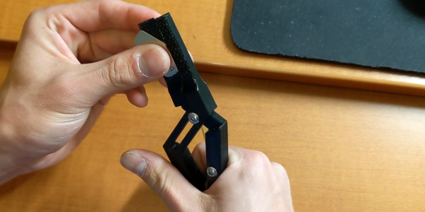
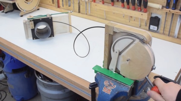
The blast door itself is held in the closed position by a piece of elastic tubing. To pull it open, he attached a bicycle cable to the blast door, with the other side attached to a latching mechanism that is the star of the show. It’s a rotating disc, with the end of the cable and operating handle attached on the outer edge. A slot track is cut in the disc, in which a pin on the end of a short arm slides. It has a few sharp corners in the track, which forces the pin to only go around in one direction, and to latch in two possible positions when released. Check out the video after the break to see it in action.