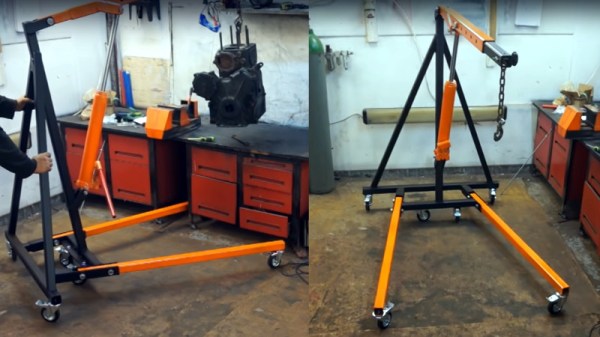
Creating A Laser Cutter From A 3D Printer

The average FDM 3D printer is not so different from your garden variety laser cutter. They’re often both Cartesian-coordinate based machines, but with different numbers of axes and mounting different tools. As [Gosse Adema] shows, turning a 3D printer into a laser cutter can actually be a remarkably easy job.

The build starts with an Anet A8 3D printer. It’s an affordable model at the lower end of the FDM printer market, making it accessible to a broad range of makers. With the help of some 3D printed brackets, it’s possible to replace the extruder assembly with a laser instead, allowing the device to cut and engrave various materials.

[Gosse] went with a 5500 mW diode laser, which allows for the cutting and engraving of wood, some plastics and even fabrics. Unlike a dedicated laser cutter there are no safety interlocks and no enclosure, so it’s important to wear goggles when the device is operating. Some tinkering with G-Code is required to get things up and running, but it’s a small price to pay to get a laser cutter on your workbench.

We’ve seen [Gosse]’s 3D printer experiments before, with the Anet A8 serving well as a PCB milling machine.

Assembling A Lathe From Not A Lot

Most people have a piece of equipment without which they consider their workshop or bench to be incomplete. For some, it is an oscilloscope, for others a bandsaw, but for many metalworkers, it is a lathe. Lathes are expensive if you are seeking a good one, quite cheap if you don’t mind a bad one, and sometimes even free if you can deal with a good one that’s very old and needs six burly friends and a forklift truck to move.

There is another way to acquire a lathe, and it’s one that [Sek Austria] demonstrates in the video below the break: build your own. It’s a fascinating demonstration of how machine tools evolved with each successive generation made by the last at every increasing precision. He achieves good-enough construction from a welded steel frame with little more than hand tools, and though his result is by no means a perfect lathe it does allow him to achieve the next level of machining precision. Off the shelf come a set of optical guide rails and linear bearings along with a chuck and tool holder, but the rest is all his. And the washing machine motor driving it is a touch of pure class, even though he is embarrassed enough to cover it with a glove for filming. Sometimes in our community, we adopt the sledgehammer to crack a nut methodology, using  CNC or similar techniques to fabricate things that can be made more speedily with less accomplished methods. We couldn’t help wincing at his hammering in the vice to create the lead screw nut bracket, though.

As homemade lathes go, this one is surprisingly conventional. Others have been fashioned from engine parts, or concrete.

Thanks [Xavier] for the tip.

Continue reading “Assembling A Lathe From Not A Lot”

You Don’t Need That Bulky CRT Oscilloscope Anymore

While it might be nice to use a $4,000 oscilloscope in a lab at a university or well-funded corporate environment, a good portion of us won’t have access to that kind of equipment in our own home shops. There are a few ways of getting a working oscilloscope without breaking the bank, though. One option is to find old CRT-based unit for maybe $50 on craigslist which might still have 60% of its original 1970s-era equipment still operational. A more reliable, and similarly-priced, way of getting an oscilloscope is to just convert a device you already have.

The EspoTek Labrador is an open-source way of converting a Raspberry Pi, Android device, or even a regular run-of-the-mill computer into a working oscilloscope. It’s a small USB device with about a two square inch PCB footprint that includes some other features as well like a signal generator and logic analyzer. It’s based on an ATxmega which is your standard Arduino-style AVR microcontroller but geared for low power usage. It looks as though it is pretty simple to use as well, and the only requirements are that you can install the software needed for the device on whatever computing platform you decide to use.

While the Labrador is available for sale at their website, it is definitely a bonus when companies offer products like this but also release the hardware and software as open source. That’s certainly a good way to get our attention, at least. You can build your own if you’d like, but if you’d rather save the time you have pre-built options. And it doesn’t hurt that most of the reviews of this product seem to be very favorable (although we haven’t tried one out ourselves). If you’d prefer an option without a company backing it, though, we have you covered there too.

Solder SMDs With A Pan O’ Sand

For those that grew up working with through-hole components, surface mount parts can be challenging to deal with. However, there are plenty of techniques out there that are more than accessible to the DIY set. With the right gear, soldering SMD boards is a snap – just get yourself a hot pan of sand (Youtube link, embedded below)!

The process starts with a professionally manufactured PCB, and accompanying stencil. All major PCB CAD packages are capable of generating stencil files these days, and many manufacturers will throw in a laser cut stencil for minimal extra cost with a PCB order. The board is first mounted on a stable surface, and has solder paste applied, before components are placed with tweezers. Perfect placement isn’t necessary, as the surface tension of the molten solder pulls components into their correct orientations. The populated board is then placed on a bed of sand in a frying pan, which is placed on an induction cooktop. The board is then heated until the solder melts, and all the components are neatly reflowed. Once allowed to cool, the board is done!

The trick is that the sand helps evenly heat the circuit board, while keeping it a safe distance away from the heat source. Results are good, and the process is far quicker than hand soldering. It’s easy to keep an eye on the process too. Of course, the traditional method is still to use the humble toaster oven, but new techniques are always useful. We’ve seen it done with a Bunsen burner, too. Video after the break.

Continue reading “Solder SMDs With A Pan O’ Sand”

Protect Yourself — And Your Project — While Working With Mains Power

When debugging ordinary low-voltage circuitry, you’re pretty safe: unless you have some really power-hungry devices that need a ton of current, there aren’t that many truly bad things that can happen, so you can take a lot of liberties with electrical-safety rules. With mains-powered devices, you don’t have this luxury, and a lack of knowledge, sloppy work practices, or simple mistakes can cost you — and your project — dearly. While you still need to know what you’re doing and use the requisite caution, [Yann Guidon]’s latest project — and entry in the 2019 Hackaday Prize —  a mains protection box, might keep simple mistakes from becoming a disaster.

There are a number of precautions you can take when working with mains power. We’ve all used the simple in-line power strip so you can quickly switch off the current, but [Yann] has included a number of devices that can be configured in different ways to experiment with mains-powered devices safely. Built into a sturdy open-topped wooden box with carry handles, the project evokes the traditional breadboard in appearance and functionality. A number of different devices are included, which could be re-configured into different topologies if needed.

[Yann] included an isolation transformer, which can be useful not only for protection against shock in case of accidentally grounding, but also for noise suppression. There is also a variac, which allows the output voltage to be adjusted over a wide range for testing. Of course, circuit breakers are a must, and current and voltage meters keep you informed about what’s going on. A big, easy-to-access switch cuts the power quickly when needed.

The (maybe) final touch is an adjustable output current limit, which is still a work in progress. Built around a current-monitoring relay and a DPDT relay wired as a latch, this allows the output to be disconnected if it draws more than a specified current, equivalent to between 10 W and 100 W. This is the perfect thing for initial testing of new projects.

So, if you’re thinking of working on mains-powered projects, have a close look at what [Yann] has assembled, and learn proper safety procedures before you begin. One place to start is with a great series by our own Jenny List about mains safety: part one and part two. Stay safe out there!

3D Printed Knife Sharpening Tool Makes The Job Easy

A sharp knife is a joy to use, but many of us are guilty of buying the cheapest kitchen tools available and rarely maintaining them. Keeping knives sharp is key to working with them both safely and effectively, but to sharpen by hand requires patience and skill. [CNC Kitchen] instead decided to use technology to get around the problem, designing a 3D-printed tool to make the job easy (Youtube video, embedded below).

The knife sharpener is a straightforward build, requiring a few simple 3D printed parts in combination with some nuts, bolts, and aluminum rods. It’s designed to use commonly sized whetstones, which makes procurement easy. The design has undergone refinement over the years, with [CNC Kitchen] adding pockets for the magnets and a spherical bearing which reduces slop in the movement.

[CNC Kitchen] reports that the tool works wonderfully, allowing even a novice to sharpen knives well. Parts are available on Thingiverse for those who wish to print their own. If however, you insist on doing things the old-fashioned way, you can get an electronic coach to help improve your technique. Video after the break.

Continue reading “3D Printed Knife Sharpening Tool Makes The Job Easy”

GlScopeClient: A Permissively-Licensed Remote Oscilloscope Utility

One of the most convenient things about modern digital oscilloscopes is that you can access the recorded data on a computer for later analysis, advanced protocol debugging, or simply the convenience of remote capture. The problem is that the software isn’t always ideal. Vendor-supplied utilities are typically closed-source and they try to nickel-and-dime you for every a-la-carte protocol and/or feature. The open-source options come with their own issues, from performance-limiting designs, to incomplete features, to license constraints. Faced with these issues, [Andrew Zonenberg] decided to take matters into his own hands and create glscopeclient, a permissively-licensed open-source remote oscilloscope utility.

The eventual goal is to allow you to do remotely anything you would normally do using the scope’s front panel, plus capture and analyze data on the computer side. The code uses a modular architecture that allows for various backends to talk to different scopes. At the moment, the only backend fully implemented is for LeCroy scopes, although this is enough to demonstrate the power of the idea. The obvious “gl” in the name gives away the secret — the code uses OpenGL for rendering, which allows for some very fancy graphics at high frame rates.

Behind the slick look, however, are some serious debugging tools. Protocol analyzers include USB, UART, JTAG, eye pattern analysis, plus FFT-based spectra with waterfall displays. The code is in GitHub, and most of the announcements and discussion seem to happen on [Andrew]’s twitter account, which you can follow @azonenberg. It’s a work-in-progress, but a serious one, and something we’re going to keep our eyes on.

You can check out a video of the program after the break.

Now, if you want to literally talk to your oscilloscope, we covered that, too.

Continue reading “GlScopeClient: A Permissively-Licensed Remote Oscilloscope Utility”