Remoticon 2021 // Rob Weinstein Builds An HP-35 From The Patent Up

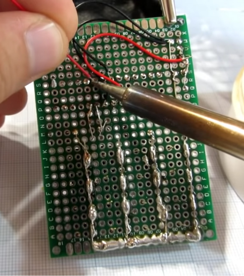
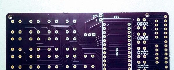
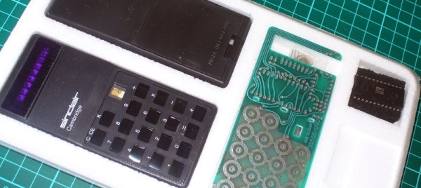
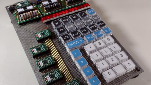
Fifty years ago, Hewlett-Packard introduced the first handheld scientific calculator, the HP-35. It was quite the engineering feat, since equivalent machines of the day were bulky desktop affairs, if not rack-mounted. [Rob Weinstein] has long been a fan of HP calculators, and used an HP-41C for many years until it wore out. Since then he gradually developed a curiosity about these old calculators and what made them tick. The more he read, the more engrossed he became. [Rob] eventually decided to embark on a three year long reverse-engineer journey that culminated a recreation of the original design on a protoboard that operates exactly like the original from 1972 (although not quite pocket-sized). In this presentation he walks us through the history of the calculator design and his efforts in understanding and eventually replicating it using modern FPGAs.

The HP patent ( US Patent 4,001,569 ) contains an extremely detailed explanation of the calculator in nearly every aspect. There are many novel concepts in the design, and [Rob] delves into two of them in his presentation. Early LED devices were a drain on batteries, and HP engineers came up with a clever solution. In a complex orchestra of multiplexed switches, they steered current through inductors and LED segments, storing energy temporarily and eliminating the need for inefficient dropping resistors. But even more complicated is the serial processor architecture of the calculator. The first microprocessors were not available when HP started this design, so the entire processor was done at the gate level. Everything operates on 56-bit registers which are constantly circulating around in circular shift registers. [Rob] has really done his homework here, carefully studying each section of the design in great depth, drawing upon old documents and books when available, and making his own material when not. For example, in the course of figuring everything out, [Rob] prepared 338 pages of timing charts in addition to those in the patent. Continue reading “Remoticon 2021 // Rob Weinstein Builds An HP-35 From The Patent Up”

Looking For Pi In The 8087 Math Coprocessor Chip

Even with ten fingers to work with, math can be hard. Microprocessors, with the silicon equivalent of just two fingers, can have an even harder time with calculations, often taking multiple machine cycles to figure out something as simple as pi. And so 40 years ago, Intel decided to give its fledgling microprocessors a break by introducing the 8087 floating-point coprocessor.

If you’ve ever wondered what was going on inside the 8087, wonder no more. [Ken Shirriff] has decapped an 8087 to reveal its inner structure, which turns out to be closely related to its function. After a quick tour of the general layout of the die, including locating the microcode engine and ROM, and a quick review of the NMOS architecture of the four-decade-old technology, [Ken] dug into the meat of the coprocessor and the reason it could speed up certain floating-point calculations by up to 100-fold. A generous portion of the complex die is devoted to a ROM that does nothing but store constants needed for its calculation algorithms. By carefully examining the pattern of NMOS transistors in the ROM area and making some educated guesses, he was able to see the binary representation of constants such as pi and the square root of two. There’s also an extensive series of arctangent and log2 constants, used for the CORDIC algorithm, which reduces otherwise complex transcendental calculations to a few quick and easy bitwise shifts and adds.

[Ken] has popped the hood on a lot of chips before, finding butterflies in an op-amp and reverse-engineering a Sinclair scientific calculator. But there’s something about seeing constants hard-coded in silicon that really fascinates us.

Two Vintage Calculators In One

The FPGA revolution that occurred within the past few decades was a boon to many people interested in “antique” electronics. The devices “wire together” logic elements as needed rather than emulating chips completely in a software layer, which makes them uniquely suited for replicating chips that are rare, no longer in production, damaged, or otherwise lost. They also make it easy to experiment with hardware, like this project which combines two antique calculators into one single unit.

The two calculators used in this combination device are the TI Datamath and the Sinclair Scientific, both released in the early 1970s, the former of which has been extensively documented and reverse engineered on at least one occasion. The reproduction from [zpekic] has a toggle that allows the user to switch between the two “modes”. This showcases the power of microprogramming and microcode, and of the FPGA platform itself. Although both modes are functional, there are still a few bugs resulting from how different the two pieces of hardware were, which is really more of an interesting facet of this project than anything.

The build is a great showcase of FPGA technology, not to mention a great read-through for understanding these two calculators and their fundamental differences in data entry and manipulation, clock cycles, memory, and everything in between. It’s worth checking out, even if you don’t plan on using a decades-old calculator in your day-to-day life.

Daisy Chained Seven Segment Art Display


This seven segment art display makes use of a 81 seven segment red common cathode LED displays. The LEDs are arranged onto 100x100mm boards that each contain an Arduino Nano and 9 seven segment displays, daisy chained through three-pin headers located on the sides of the boards. The pins (power, ground, and serial) provide the signals necessary for propagating a program across each of the connected boards.

The first board – with two Arduino Nanos – sends instructions for which digits to light and drives the display, sending the instructions over to the next board on the chain.

In a multiplexed arrangement, a single Arduino Nano is able to drive up to 12 seven segment displays, but only 9 needed to be driven for the program, keeping D13’s built in LED and the serial pins free. Since no resistors are featured on the boards, current limiting is done through software. This was inspired by the Bubble LED displays on the Sinclair Scientific Calculator, and was done in order to achieve a greater brightness by controlling the current through the duty cycle.

The time between digits lighting up is 2ms, giving them some time to cool down. The animations in the demos featured falling and incrementing digits, as well as a random number generator using a linear feedback shift register.

Continue reading “Daisy Chained Seven Segment Art Display”

Pocket Sized Arduino Calculator Makes A Great First Project

We’ve all got calculators on our phones, in our web browsers, and even in the home “assistant” that’s listening in on your conversations all day on the off chance you blurt out a math question is can solve for you. The most hardcore among us might even still have a real calculator kicking around. So in that light, building your own DIY calculator might not seem too exciting. But we can’t deny this Arduino calculator project by [Danko Bertović] would look good sitting on the bench.

In the video after the break, [Danko] walks us through the creation of the calculator, from placing all the through-hole components to writing the code that pulls it all together. Special attention is given to explaining the wiring, making this is a good project for those just getting started on their digital hacking journey. It also helps that the whole thing is put together on perfboard with jumper wires; no PCB fabrication required for this one.

For the user interface, [Danko] is using an array of 17 tactile switches for the keyboard and a very crisp 128×32 I2C OLED display. Beyond the battery, a crystal, and a handful of passive components, that’s about all the support hardware it takes to put this project together. You don’t even need an enclosure: a second piece of perfboard and some standoffs are used to sandwich the battery and fragile wiring inside.

Of course, the star of the show is the ATmega328P microcontroller, which is mounted in a place of honor right under the OLED screen. The chip gets programmed in an Arduino Uno and then transplanted into the calculator, a neat trick if you don’t have a dedicated programmer handy. Given how cheap Arduino clones can be had online, this is becoming a more common practice.

The construction of this calculator reminds us a bit of the DIY Sinclair scientific calculator we looked at over the summer. But if you want to see the peak of homebrew calculator technology, this Raspberry Pi powered build is tough to beat.

Continue reading “Pocket Sized Arduino Calculator Makes A Great First Project”

How To Design Custom Shaped Boards In Fritzing

If you’re looking to get started in designing a few PCBs, you could use one of the many software packages that allow you to create a PCB quickly, easily, and with a minimum amount of fuss. You could also use Fritzing.

Fritzing is terribad and you shouldn’t use it, but that doesn’t mean you still can’t abuse Fritzing to make it do what you want. [Arduino Enigma] recently posted a tutorial on how to design custom PCB shapes for Fritzing. Yes, Fritzing is no longer limited to rectangular PCBs with sharp corners. You can make PCBs in any shape with Fritzing, provided you spend a few hours futzing about with Inkscape.

The goal for this project was to create a rectangular board without any sharp corners for [Arduino Enigma]’s Sinclair Scientific Calculator Emulator. Fritzing can make a board in the shape of a rectangle, in fact, that’s all it can do, but [Arduino Enigma] wanted a rectangle with radiused corners. After hours of work, we have the writeup on how to do it.

The imported board, with 3mm radiused corners.

The process to create a custom-shaped board, in this case, a rectangle with a 3mm radius on the corners, is simple. First, draw a rectangle of the desired shape, then draw even more rectangles as a sublayer of the current layer. Fritzing requires the layer ID to be named ‘board’, ‘silkscreen’ and ‘silkscreen0’, but this cannot be changed in Inkscape itself — you’ll need to edit the file with a text editor. After creating three layers, each containing the shape you want, simply trim the size of the page to the size of the board. Save the file, edit the file in a text editor, and click save. Launch Fritzing, load an image file, and select the SVG you’ve been working on. In just twenty or thirty quick steps, you too can import any shape you can imagine into Fritzing.

There is one pain point to this process. Editing the layer name manually with a text editor pushes this Fritzing hack from a baroque workaround into something that makes us all question the state of Open Source standards. Unfortunately, this is required because Inkscape does not use layer names as the ID in an SVG file. No, it doesn’t make sense, but that’s just the way it is.

For any other PCB design tool, creating a custom-shaped board is simply a matter of drawing a few lines. Fritzing is different, though. The top copper layer is represented as orange, and the bottom copper layer is yellow, a UI decision that doesn’t make sense, even if you aren’t colorblind. Putting more than two layers of copper on a Fritzing board is impossible. Fritzing is a tool you should avoid for PCB layout. That said, [Arduino Enigma] figured out how to do something in Fritzing that you’re not supposed to be able to do and that’s pretty cool.

Build A Calculator, 1974 Style

Last month we touched upon the world of 1970s calculators with a teardown of a vintage Sinclair, and in the follow-up were sent an interesting link: a review of a classic Sinclair calculator kit from [John Boxall]. It’s a few years old now, from 2013, but since it passed us by at the time and there was clearly some interest in our recent teardown, it’s presented here for your interest.

It seems odd in 2017 that a calculator might be sold as a kit, but when you consider that in the early 1970s it would have represented an extremely expensive luxury purchase it makes some sense that electronics enthusiasts who were handy with a soldering iron might consider the cost saving of self-assembly to be worthwhile. The £24.95 price tag sounds pretty reasonable but translates to nearly £245 ($320) in today’s terms so was hardly cheap. The calculator in question is a Sinclair Cambridge, the arithmetic-only predecessor to the Sinclair Scientific we tore down, and judging by the date code on its display driver chip it dates from September 1974.

As a rare eBay find that had sat in storage for so long it was clear that some of the parts had suffered a little during the intervening years. The discrete components were replaced with modern equivalents, including a missing 1N914 diode, and the display was secured in its flush-fitting well in the board with wire links. The General Instrument calculator chip differs from the Texas Instruments part used in the Scientific, but otherwise the two calculators share many similarities. A full set of the notoriously fragile Sinclair battery clips are in place, with luck they’ll resist the urge to snap. A particularly neat touch is the inclusion of a length of solder and some solder wick, what seems straightforward to eyes used to surface-mount must have been impossibly fiddly to those brought up soldering tube bases.

The build raises an interesting question: is it sacrilege to take a rare survivor like this kit, and assemble it? Would you do it? We’d hesitate, maybe. But having done so it makes for a fascinating extra look at a Sinclair Cambridge, so is definitely worth a read. If you want to see the calculator in action he’s posted a video which we’ve put below the break, and if you need more detail including full-resolution pictures of the kit manual, he’s put up a Flickr gallery.

Continue reading “Build A Calculator, 1974 Style”