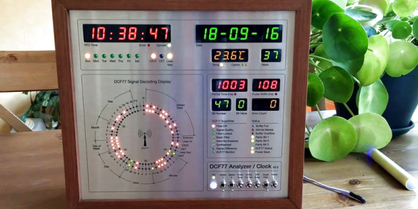
Clocks that read time via received radio signals have several advantages over their Internet-connected, NTP-synchronised brethren. The radio signal is ubiquitous and available over a fairly large footprint extending to thousands of kilometres from the transmitting antennae. This allows such clocks to work reliably in areas where there is no Internet service. And compared to GPS clocks, their front-end electronics and antenna requirements are much simpler. [Erik de Ruiter]’s DCF77 Analyzer/Clock is synchronised to the German DCF77 radio signal, which is derived from the atomic clocks at PTB headquarters. It features a ton of bells and whistles, while still being simple to build. It’s a slick piece of German hacker engineering that leaves us amazed.
Among the clock functions, it shows time, day of the week, date, CET/CEST modes, leap year indications and week numbers. The last is not part of the DCF77 protocol but is calculated via software. The DCF77 analyzer part has all of the useful information gleaned from the radio signals. There are displays for time period, pulse width, a bit counter, bit value indicator (0/1) and an error counter. There are two rings of 59 LEDs each that provide additional information about the DCF77 signal. A PIR sensor on the front panel helps put the clock in power save mode. Finally, there is a whole bunch of indicator LEDs and a bank of switches to control the various functions. On the rear panel, there are RJ45 sockets for the DCF77 receiver antenna board, temperature sensor and FTDI serial, a bunch of audio sound board controls, reset switches and a mode control switch.
His build starts with the design and layout of the enclosure. The front panel layout had to go through a couple of iterations before he was satisfied with the result. The final version was made from aluminium-coated sandwich-panel. He used an online service to photo-etch the markings, and then a milling machine to carve out the various windows and mounting holes. The rear panel is a tinted acrylic with laser engraving, which makes the neatly laid out innards visible for viewers to appreciate. The wooden frame is made from 40-year-old Mahogany, sourced from an old family heirloom desk. All of this hard work results in a really professional looking product.
The electronics are mostly off the shelf modules, except for the custom built LED driver boards. The heart of the device is an Arduino Mega because of the large number of outputs it provides. There are seven LED driver boards based around the Maxim 7221 (PDF) serial interface LED drivers – two to drive the inner and outer ring LEDs, and the others for the various seven-segment displays. The numerous annunciator LEDs are driven directly from the Arduino Mega. His build really comes together by incorporating a noise resilient DCF77 decoder library by [Udo Klein] which is running on a separate Arduino Uno. All of his design source files are posted on his GitHub repository and he hopes to publish an Instructable soon for those who would like to build one of their own.
In the first video below, he walks through the various functions of the clock, and in the second one, gives us a peek in to its inside. Watch, and be amazed.
Thanks for the tip, [Nick]
Continue reading “Well Engineered Radio Clock Aces Form And Function” →
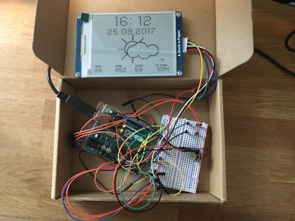
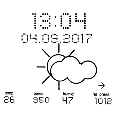 [Fandonov] has created a weather station project with an Arduino Uno at its heart and a Waveshare e-ink display as its face to the world, and as its write-up (PDF) describes, it provides an insight into both some of the quirks of these displays, and into weather forecasting algorithms.