All-Band Radio Records Signals, Plays MP3s

In these days of everything-streaming, it’s great to see an old school radio build. It’s even better when it’s not old-school at all, but packed full of modern ICs and driven by a micro-controller like the dsPIC in [Minh Danh]’s dsMP3 build. Best of all is when we get enough details that the author needs two blog posts — one for hardware, and one for firmware — like [Minh Danh] has done.

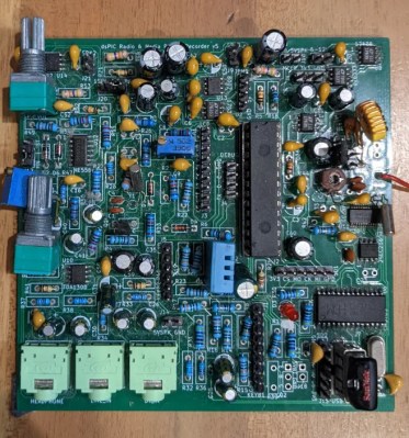
This build does it all: radio, MP3 playback, and records incoming signals. The radio portion of the build is driven by an Si4735, which allows for receiving both in FM and AM — with all the AM bands, SW, MW and LW available. The FM section does support RDS, though because [Minh Danh] ran out of pins on the dsPIC, isn’t the perfect implementation.

Just look at that thru-hole goodness.

The audio section is a good intro to audio engineering if you’ve never done a project like this: he’s using a TDA1308 for headphones, which feeds into a NS8002 to drive some hefty stereo speakers– and he tells you why he selected those chips, as well as providing broken-out schematics for each. Really, we can’t say enough good things about this project’s documentation.

That’s before we get to the firmware, where he tells us how he manages to get the dsPIC to read out MP3s from a USB drive, and write WAVs to it. One very interesting detail is how he used the dsPIC’s ample analog inputs to handle the front panel buttons on this radio: a resistor ladder. It’s a great solution in a project that’s full of them.

Of course we’ve seen radio receivers before, and plenty of MP3 players, too — but this might be the first time we’ve seen an electronic Swiss army knife with all these features, and we’re very glad [Minh Danh] shared it with us.

Continue reading “All-Band Radio Records Signals, Plays MP3s”

Crossing Commodore Signal Cables On Purpose

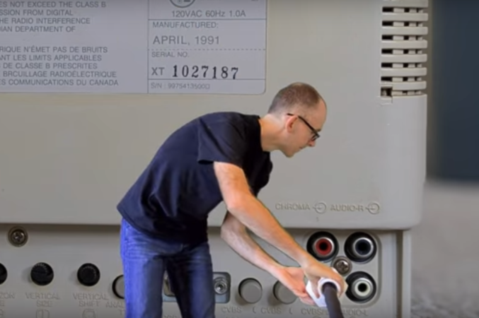
On a Commodore 64, the computer is normally connected to a monitor with one composite video cable and to an audio device with a second, identical (although uniquely colored) cable. The signals passed through these cables are analog, each generated by a dedicated chip on the computer. Many C64 users may have accidentally swapped these cables when first setting up their machines, but [Matthias] wondered if this could be done purposefully — generating video with the audio hardware and vice versa.

Getting an audio signal from the video hardware on the Commodore is simple enough. The chips here operate at well over the needed frequency for even the best audio equipment, so it’s a relatively straightforward matter of generating an appropriate output wave. The audio hardware, on the other hand, is much less performative by comparison. The only component here capable of generating a fast enough signal to be understood by display hardware of the time is actually the volume register, although due to a filter on the chip the output is always going to be a bit blurred. But this setup is good enough to generate large text and some other features as well.

There are a few other constraints here as well, namely that loading the demos that [Matthias] has written takes so long that the audio can’t be paused while this happens and has to be bit-banged the entire time. It’s an in-depth project that shows mastery of the retro hardware, and for some other C64 demos take a look at this one which is written in just 256 bytes.

Continue reading “Crossing Commodore Signal Cables On Purpose”

DIY Record Cutting Lathe Is Really Groovy

Back in the day, one of the few reasons to prefer compact cassette tape to vinyl was the fact you could record it at home in very good fidelity. Sure, if you had the scratch, you could go out and get a small batch of records made from that tape, but the machinery to do it was expensive and not always easy to come by, depending where you lived. That goes double today, but we’re in the middle of a vinyl renaissance! [ronald] wanted to make records, but was unable to find a lathe, so decided to take matters into his own hands, and build his own vinyl record cutting lathe.

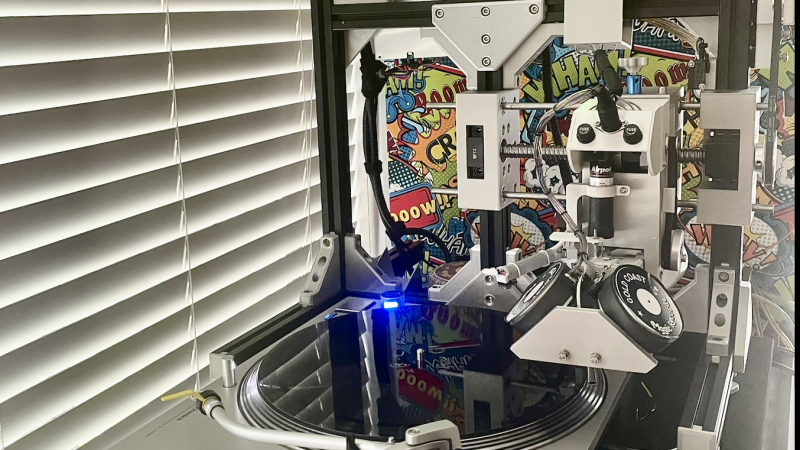
photograph of [ronald's] setup
[ronald’s] record cutting lathe looks quite professional.
It seems like it should be a simple problem, at least in concept: wiggle an engraving needle to scratch grooves in plastic. Of course for a stereo record, the wiggling needs to be two-axis, and for stereo HiFi you need that wiggling to be very precise over a very large range of frequencies (7 Hz to 50 kHz, to match the pros). Then of course there’s the question of how you’re controlling the wiggling of this engraving needle. (In this case, it’s through a DAC, so technically this is a CNC hack.) As often happens, once you get down to brass tacks (or diamond styluses, as the case may be) the “simple” problem becomes a major project. Continue reading “DIY Record Cutting Lathe Is Really Groovy”

Designing A Tone Control Properly

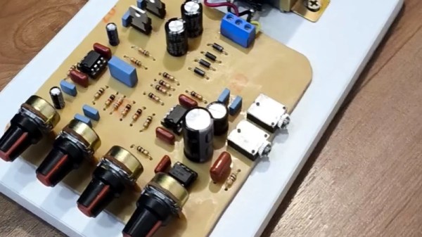
Many years ago, audio equipment came with a tone control, a simple RC filter that would cut or boost the bass to taste. As time passed, this was split into two controls for bass and treble, and then finally into three for bass, mid, and treble. When audiophile fashion shifted towards graphic equalisers, these tone controls were rebranded as “3-band graphic equalisers”, a misleading term if ever we heard one. [Gabriel Dantas] designed one of these circuits, and unlike the simple passive networks found on cheap music centres of old, he’s doing a proper job with active filters.

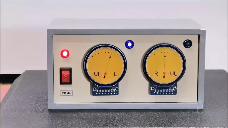
The write-up is worth a read even if you are not in the market for a fancy tone control, for the basic primer it gives on designing an audio filter. The design contains, as you might expect, a low-pass, a bandpass, and a high-pass filter. These are built around TL072 FET-input op-amps, and an LM386 output stage is added to drive headphones.

The final project is built on a home-made PCB, complete with mains power supply. Audiophiles might demand more exotic parts, but we’re guessing that even with these proletarian components it will still sound pretty good. Probably better than the headphone amplifier featured in a recent project from a Hackaday writer, at least. There’s a build video, below the break.

Continue reading “Designing A Tone Control Properly”

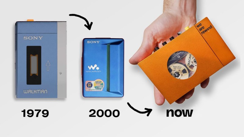
An image showing an original grey and blue Sony Walkman with the text "1970" below it, and an arrow pointing to the right of it at a much smaller blue Walkman with the text "2000" underneath it, and a final arrow pointing to the right to a bright orange cassette player by We Are Rewind in a man's hand with the text "now" beneath it.

Why Are Cassette And CD Players So Big Now?

The early 2000s were the halcyon days of physical media. While not as svelte as MP3 players became, why are those early 2000s machines smaller than all the new models popping up amidst the retro audio craze?

We’ve bemoaned the end of the electromechanical era before, and the Verge recently interviewed the people at We Are Rewind and Filo to get the skinny on just why these newer cassette and CD players aren’t as small as their predecessors. It turns out that all currently produced cassette players use the same mechanism with some small tweaks in materials (like metal flywheels in these higher quality models) because the engineering required to design a smaller and better sounding alternative isn’t warranted by the niche nature of the cassette resurgence.

A similar fate has befallen the laser head of CD mechanisms, which is why we don’t have those smooth, rounded players anymore. Economies of scale in the early 2000s mean that even a cheap player from that era can outperform a lot of the newer ones, although you won’t have newer features like Bluetooth to scandalize your audiophile friends. A new Minidisc player is certainly out of the question, although production of discs only ended this February.

If you’re looking to get back into cassettes, this masterclass is a good place to start. If you don’t fancy any of the players the Verge looked at, how about rolling your own incarnation with the guts from a vintage machine or just going for the aesthetic if cassettes aren’t your jam?

Continue reading “Why Are Cassette And CD Players So Big Now?”

Copying Commodore Data Tapes, 40 Years Late

Unless you handle the backups for a large corporation, bank, or government entity, you likely haven’t stored much data to tape recently. But magnetic storage used to be fairly mainstream back in the 1980s for all kinds of computer programs. Plenty of computers used standard cassette tapes for this too but you couldn’t just copy them with standard audio equipment. You’d need something like this 1560 datasette from [Jan].

The core problem with using Hi-Fi equipment to copy tapes storing data instead of audio is that data tapes need to be much more precise in order to avoid losses that might not be noticeable in an audio recording. In the 80s computer companies like Commodore built tape drives specifically for their computers, so [Jan]’s project uses two of these 1530 drives to build this “1560” datasette. (No working 1530 hardware was harmed in this build.) An inverter circuit in one tape deck is used to provide the signal to write the data to the other tape, reliably copying data from these data tapes in a way Hi-Fi never could.

[Jan] does lament not having something like this back in the 80s when the Commodore was in its heyday, but there’s still a dedicated retrocomputing scene for these machines that will get plenty of use out of projects like this. If you need to go the other direction in time, there are also interfaces that allow data tapes from old Commodores to be read by modern computers with USB.

Continue reading “Copying Commodore Data Tapes, 40 Years Late”

Bringing A Current Dumping Amplifier Back To Life

Over the years there have been many different audio amplifier designs which have found favour for a while and then been supplanted by newer ideas. One of them has crossed the bench of [Jazzy Jane], it’s a current dumping amplifier from the mid-1980s. A nicely-done home-made project on stripboard mounted on a wooden base board, it sports a power supply, RIAA pre-amp board, and the amplifier itself.

The current dumping amplifier is one that combines a small class A amplifier with a hefty class B one, and through feedback trickery uses the combination to remove the crossover distortion of the class B stage. It’s a simple yet elegant circuit with fewer parts than an equivalent class AB amplifier, and there was a time back in the day when it was all the rage. This one has an op-amp providing the class A part and a complimentary pair of Darlington pairs as the class B.

The video below the break shows the process of bringing the amp back to life, a process mostly concerned with the power supply. There are a set of tantalum capacitors which have failed, and the replacements she’s using turn out to have problems too. They’re a period part for a project of this age, but we might have been tempted to go for another capacitor type here.

The result is an unusual amplifier, brought back to life. You may have seen [Jane] feature here before, with her 1950s signal generator.

Continue reading “Bringing A Current Dumping Amplifier Back To Life”