Chuck peddle father of 6502

Honoring Chuck Peddle; Father Of The 6502 And The Chips That Went With It

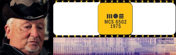
Chuck Peddle, the patriarch of the 6502 microprocessor, died recently. Most people don’t know the effect that he and his team of engineers had on their lives. We often take the world of microprocessor for granted as a commonplace component in computation device, yet there was a time when there were just processors, and they were the size of whole printed circuit boards.

Chuck had the wild idea while working at Motorola that they could shrink the expensive processor board down to an integrated circuit, a chip, and that it would cost much less, tens of dollars instead of ten thousand plus. To hear Chuck talk about it, he got a cease-and-desist letter from the part of Motorola that made their living selling $14,000 processor boards and to knock off all of the noise about a $25 alternative.

In Chuck’s mind this was permission to take his idea, and the engineering team, elsewhere. Chuck and his team started MOS Technologies in the 1970’s in Norristown PA, and re-purposed their work on the Motorola 6800 to become the MOS 6502. Lawsuits followed.

Continue reading “Honoring Chuck Peddle; Father Of The 6502 And The Chips That Went With It”

High-Speed PCB Design Hack Chat With Bil Herd

Join us on Wednesday, September 25 at noon Pacific for the High-Speed PCB Design Hack Chat with Bil Herd!

Printed circuits have become so commoditized that we seldom think much about design details. EDA software makes it easy to forget about the subtleties and nuances that make themselves painfully obvious once your design comes back from the fab and doesn’t work quite the way you thought it would.

PCB design only gets more difficult the faster your circuit needs to go, and that’s where a depth of practical design experience can come in handy. Bil Herd, the legendary design engineer who worked on the Commodore C128 and Plus4/264 computers and many designs since then, knows a thing or two in this space, and he’s going to stop by the Hack Chat to talk about it. This is your chance to pick the brain of someone with a wealth of real-world experience in high-speed PCB design. Come along to find out what kind of design mistakes are waiting to make your day miserable, and which ones can be safely ignored. Spoiler alert: square corners probably don’t matter.

join-hack-chatOur Hack Chats are live community events in the Hackaday.io Hack Chat group messaging. This week we’ll be sitting down on Wednesday, September 25 at 12:00 PM Pacific time. If time zones have got you down, we have a handy time zone converter.

Click that speech bubble to the right, and you’ll be taken directly to the Hack Chat group on Hackaday.io. You don’t have to wait until Wednesday; join whenever you want and you can see what the community is talking about. Continue reading “High-Speed PCB Design Hack Chat With Bil Herd”

Video: Putting High Speed PCB Design To The Test

Designing circuit boards for high speed applications requires special considerations. This you already know, but what exactly do you need to do differently from common board layout? Building on where I left off discussing impedance in 2 layer Printed Circuit Board (PCB) designs, I wanted to start talking about high speed design techniques as they relate to PCBs.  This is the world of multi-layer PCBs and where the impedance of both the Power Delivery Network (PDN) and the integrity of the signals themselves (Signal Integrity or SI) become very important factors.

I put together a few board designs to test out different situations that affect high speed signals. You’ve likely heard of vias and traces laid out at right angles having an impact. But have you considered how the glass fabric weave in the board itself impacts a design? In this video I grabbed some of my fanciest test equipment and put these design assumptions to the test. Have a look and then join me after the break for more details on what went into this!

Continue reading “Video: Putting High Speed PCB Design To The Test”

Inductance In PCB Layout: The Good, The Bad, And The Fugly

When current flows through a conductor it becomes an inductor, when there is an inductor there is an electromagnetic field (EM). This can cause a variety of issues during PCB layout if you don’t plan properly, and sometimes we get burned even when we think we have planned for unwanted inductance and the effects that come with them.

When doing high speed logic we need to be able to deliver sudden changes in current to the devices if we want to have proper switching times and logic levels. Unfortunately inductance is usually not a friend in these circumstances as it resists those sudden changes in current. If the high speed devices are driving capacitive loads, which themselves are resisting changes in voltage, even more instantaneous current is needed.

Simply put, inductors resist a change of current, and can act as a low pass filter when in series with the signal or power supply flow. Inductors do this by storing energy in the flux surrounding the conductor. Alternatively capacitors resist a change in voltage (again by storing energy) and can act as a high pass filter when in series with the signal. This makes them a valuable tool in the fight against unwanted inductance in power supply distribution.

In the video below, and the remainder of this article, I’m going to dive into the concept of inductance and how it affects our design choices when laying out circuit boards.

Continue reading “Inductance In PCB Layout: The Good, The Bad, And The Fugly”

How To Do Beautiful Enclosures With Custom Fiberglass

There are times when I feel the need to really make a mess. When I think of making messes with a degree of permanency, I think of fiberglass. I also really like the smell, reminds me of a simpler time in 8th grade shop class. But the whole process, including the mess, is worth it for the amazing shapes you can produce for speaker pods and custom enclosures.

Utilizing fiberglass for something like a custom speaker pod for a car is not difficult, but it does tend to be tedious when it comes to the finishing stages. If you have ever done bodywork on a car you know what kind of mess and effort I am talking about. In the video below, I make a simple speaker pod meant for mounting a speaker to the surface of something like a car door.

You can also use a combination of wood and fiberglass to make subwoofer cabinets that are molded to the area around them. You can even replace your entire door panel with a slick custom shaped one with built in speakers  if you’re feeling adventuresome.

Continue reading “How To Do Beautiful Enclosures With Custom Fiberglass”

Friday Hack Chat: Electronics Design And Naming A Puppy

For one reason or another, Hackaday has an extended family of ridiculously capable contributors. One of the most illustrious is [Bil Herd], Commodore refugee, electronic engineer, medic, and all-around awesome guy. He’ll be joining us over on Hackaday.io this Friday for a Hack Chat on Electronics Design.

This Friday, we’re hosting a Hack Chat with [Bil]. If you want to talk Commodore, this is the guy. If you want to talk about PLAs and programmable digital logic, this is the guy. If you want to know how to build a system from scratch in just a few months, [Bil]’s your man. [Bil] has decades of experience and his design work was produced by the millions. You’ll rarely come across someone with as much experience, and he’ll be in our Hack Chat this Friday.

[Bil] has a long career in electronics design, beginning with fixing CB radios and televisions back when fixing TVs was still a thing. Eventually, he worked his way up the engineering ladder at Commodore Business Machines where he designed the Commodore TED machines and the amazing Commodore 128.

After surviving Commodore, [Bil] has worked at a trauma center in Camden, NJ, flown with medics in the Army, and eventually came over to Hackaday where he produces videos from subjects ranging from direct digital synthesis, programmable logic, active filters, and how CMOS actually works. Basically, if it involves electronics, [Bil] knows what’s up.

Oh, as an added bonus, we get to name a puppy this week. [Bil] got a new puppy and it needs a name. Send in your suggestions!

Here’s How To Take Part:

join-hack-chatOur Hack Chats are live community events on the Hackaday.io Hack Chat group messaging. This hack chat will take place at noon Pacific time on Friday, June 16th. Confused about where and when ‘noon’ is? Here’s a time and date converter!

Log into Hackaday.io, visit that page, and look for the ‘Join this Project’ Button. Once you’re part of the project, the button will change to ‘Team Messaging’, which takes you directly to the Hack Chat.

You don’t have to wait until Friday; join whenever you want and you can see what the community is talking about

OBDII to Speed Pulse: Atmel ICE

Building An OBD Speed Pulse: Behold The ICE

I am a crappy software coder when it comes down to it. I didn’t pay attention when everything went object oriented and my roots were always assembly language and Real Time Operating Systems (RTOS) anyways.

So it only natural that I would reach for a true In-Circuit-Emulator (ICE) to finish of my little OBDII bus to speed pulse generator widget. ICE is a hardware device used to debug embedded systems. It communicates with the microcontroller on your board, allowing you to view what is going on by pausing execution and inspecting or changing values in the hardware registers. If you want to be great at embedded development you need to be great at using in-circuit emulation.

Not only do I get to watch my mistakes in near real time, I get to make a video about it.

Getting Data Out of a Vehicle

I’ve been working on a small board which will plug into my car and give direct access to speed reported on the Controller Area Network (CAN bus).

To back up a bit, my last video post was about my inane desire to make a small assembly that could plug into the OBDII port on my truck and create a series of pulses representing the speed of the vehicle for my GPS to function much more accurately. While there was a wire buried deep in the multiple bundles of wires connected to the vehicle’s Engine Control Module, I have decided for numerous reasons to create my own signal source.

At the heart of my project is the need to convert the OBDII port and the underlying CAN protocol to a simple variable representing the speed, and to then covert that value to a pulse stream where the frequency varied based on speed. The OBDII/CAN Protocol is handled by the STN1110 chip and converted to ASCII, and I am using an ATmega328 like found on a multitude of Arduino’ish boards for the ASCII to pulse conversion. I’m using hardware interrupts to control the signal output for rock-solid, jitter-free timing.

Walk through the process of using an In-Circuit Emulator in the video below, and join me after the break for a few more details on the process.

Continue reading “Building An OBD Speed Pulse: Behold The ICE”