Exploring The Hall Effect For Haptic Feedback PS4 Joysticks

Modern gaming console controllers aren’t without their annoyances — Joy-Con drift, anyone? The problems might stem from design deficiencies, but we suspect that user enthusiasm and the mechanical stress it can introduce might play a significant role as well. Either way, [Marius Heier] decided to take a look at what would be required to build a better joystick and came up with some interesting results.

The first video below lays the basic groundwork, with a bunch of experiments with 3-axis Hall effect sensors, specifically the Texas Instruments TMAG5273 and TMAG5170. They’re essentially the same sensor with different interfaces — SPI for the 5170 and I2C for the 5273. Using just one of these sensors, he was able to build a joystick with the usual X- and Y- axis control, but also with a rotary axis. What’s more, he built a motorized version using two NEMA 17 steppers to mechanically drive the stick back to center.

The joystick is bulky, but it looks like he’s got plans for a much smaller one with [Carl Bugeja]-style PCB motors that should fit into a PS4 controller. That’s the subject of the second video below, which uses a different Hall sensor — an Allegro A1304 — and is mainly concerned with getting the output of a non-motorized but considerably miniaturized joystick stick talking the language that the controller expects. It’s not a simple process, but it seems to be coming along nicely, and we’ll be watching progress closely.

Continue reading “Exploring The Hall Effect For Haptic Feedback PS4 Joysticks”

This Electric Outboard Conversion Makes For A Quiet Day On The Water

Nothing beats a day on the lake in a little boat with an outboard motor putt-putting along behind you. It’s great fun, if perhaps a little noisy with all that putting going on. And maybe that oily sheen on the water in your wake is not so nice. it could be that the fish are a little annoyed with your putting, too. Come to think of it, outboard motors are a bit of a problem.

Fortunately there’s a better way, like converting an old outboard motor to electric. It comes to us by way of [Anton], who happened upon the perfect donor platform — a 5-hp outboard by Crescent, sporting a glorious 1970s color scheme and a motor housing shell perfect for modding. He started by ripping the old engine and drivetrain out of the housing to make room for the BLDC motor and its driver. The motor was a project in itself; [Anton] rewound the original stator with much thicker wire and changed the coil configuration to milk as much torque as possible out of it. What started as a 180-kv motor ended up at 77 kv with much more copper and new Hall sensors for the controller. He also put a ton of effort into waterproofing the motor with epoxy resin. With a 3D-printed prop and a streamlined fairing, the new motor looks quite at home on the outboard. In fact, the whole thing barely looks customized at all — the speed control is even right on the tiller where you’d expect it.

The video below shows the build and a test run, plus an analysis of the problems encountered, chief of which is water intrusion. But as [Anton] rightly points out, that’s easily solved by reusing the original driveshaft and mounting the motor above the waterline, like this. Still, we like the look of this, and the idea of knocking around on the water nearly silently seems wonderful.

Continue reading “This Electric Outboard Conversion Makes For A Quiet Day On The Water”

An In-Depth Look At The Haptic Smart Knob

At Hackaday, we love those times when we get a chance to follow up on a project that we’ve already featured. Generally, it’s because the project has advanced in some significant way, which is always great to see. Sometimes, though, new details on the original project are available, and that’s where we find ourselves with [Scott Bez] and his haptic smart knob project.

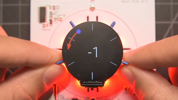
Alert readers may recall [Scott]’s announcement of this project back in March. It made quite a splash, with favorable comments and a general “Why didn’t I think of that?” vibe. And with good reason; the build quality is excellent, and the idea is simple yet powerful. By attaching a knob to the shaft of a brushless DC motor and mounting a small circular LCD screen in the middle, [Scott] came up with an input device that could be reprogrammed on the fly. The BLDC can provide virtual detents at any interval while generating haptic feedback for button pushes, and the LCD screen can provide user feedback.

But how is such a thing built? That’s the subject of the current video, which has a ton of neat design details and build insights. The big challenge for [Scott] was supporting the LCD screen in the middle of the knob while still allowing the knob — and the motor — to rotate. Part of the solution was, sadly, a hollow-shaft motor that was out of stock soon after he released this project; hopefully a suitable replacement will be available soon. Another neat feature is the way [Scott] built tiny strain gauges into the PCB itself, which pick up the knob presses that act as an input button. We also found the way button press haptics are provided by a quick jerk of the motor shaft very clever.

This is one of those projects that seems like a solution waiting for a problem, and something that you’d build just for the coolness factor. Hats off to [Scott] for following up a sweet build with equally juicy details.

Continue reading “An In-Depth Look At The Haptic Smart Knob”

OpenMower: Open Source Robotic Lawn Mower With RTK GPS

Robotic mowers are becoming a common sight in some places, enabled by the cost of motors and the needed control electronics being much lower, thanks to the pace of modern engineering. But, in many cases, they still appear to be really rather dumb, little more than a jacked up bump-and-go with a spinning blade. [Clemens Elflein] has taken a cheap, dumb mower and given it a brain transplant based around a Raspberry Pi 4 paired up with a Raspberry Pi Pico for the real time control side of things. [Clemens] is calling this OpenMower, with the motivation to create an open source robot mower controller with support for GPS navigation, using RTK for extra precision.

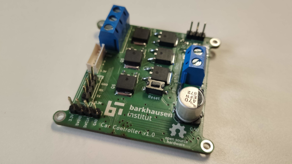
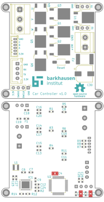
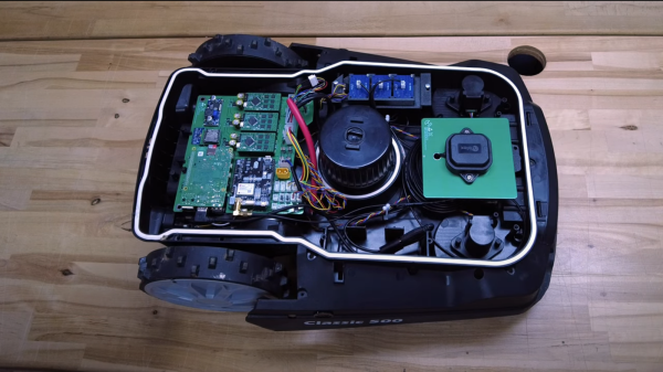
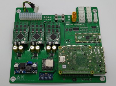
The donor robot was a YardForce Classic 500, and after inspection of the control PCB, it looks like many other robot mower models are likely to use the same controller and thus be compatible with the openmower platform. A custom mainboard houses the Pi 4 and Pico, an ArduSimple RTK GPS module (giving a reported navigational accuracy of 1 cm,) as well as three BLDC motor drivers for the wheels and rotor. Everything is based on modules, plugging into the mainboard, reducing the complexity of the project significantly. For a cheap mower platform, the Yardforce unit has a good build quality, with connectors everywhere, making OpenMower a plug and play solution. Even the user interface on top of the mower was usable, with a custom PCB below presenting some push buttons at the appropriate positions.

OpenMower mainboard

Motor control is courtesy of the xESC project, which provides FOC motor control for low cost, interfacing with the host controller via a serial link. This is worth looking into in its own right! On the software side of things, [Clemens] is using ROS, which implements the low level robot control, path planning (using code taken from Slic3r) as well a kinematics constraints for object avoidance. The video below, shows how simple the machine is to operate — just drive it around the perimeter of lawn with a handheld controller, and show it where obstacles such as trees are, and then set it going. The mower is even capable of mowing multiple lawns, making the journey between them automatically!

Robotic mower projects are not new around here, here’s the mysterious TK with an interesting take, another using RTK GPS for good (or possibly bad) and quite probably the jankiest one we’ve seen in a while, which uses a LoRa base-station to transmit RTK corrections. We’d recommend keeping well away from that last one.

Continue reading “OpenMower: Open Source Robotic Lawn Mower With RTK GPS”

Giant PC fan

3D-Printed Parts Let You Assemble Your Own Biggest Fan

It’s getting close to the time of year when we need to start carefully vetting projects here at Hackaday. After all, nobody likes to get punked by an early April Fool’s joke. But as silly as this outsized PC fan looks, it sure seems like a legit build, if a bit on the pointless side.

Then again, perhaps pointless is too harsh a word to use. This 500-mm fan is by [Angus] over at Maker’s Muse, and it represents a lot of design work to make it buildable, as well as workable and (mostly) safe. Using both CNC-cut MDF and printed parts, the fan is an embiggened replica of a normal-sized case fan. The fan’s frame had to be printed in four parts, which lock together with clever interlocking joints. Each of the nine blades locks into a central hub with sturdy-looking dovetails.

And sturdy is important, as the fan is powered by a 1,500 Watt brushless DC motor. With a 4:1 reduction thanks to a printed gear train, the fan spins at around 3,300 RPM, which makes a terrifying noise. There’s a little bit of “speed-wobble” evident, but [Angus] managed to survive testing. The fan, however, did not — the 3D-printed gears self-destructed after a full-speed test, but not before the fan did its best wind tunnel imitation. And the RGB LEDs looked great.

This one reminds up of something we might see [Ivan Miranda] come up with. In fact, his super-sized 3D printer might have been just the thing to shorten [Angus]’ print times.

Continue reading “3D-Printed Parts Let You Assemble Your Own Biggest Fan”

Haptic Smart Knob Does Several Jobs

A knob is a knob, a switch is a switch, and that’s that, right? And what about those knobs that have detents, set in stone at the time of manufacturing? Oh, and those knobs that let you jog left to right and then snap back to center — that can’t be modified…right? Well, you likely know where this is going, and in the video below the break, [scottbez1] shows off a new open source haptic input knob that can be all of these things with just some configuration changes!

The list of possibilities is long: virtual snap points, virtual spring loading, virtual detents, virtual end points. It’s a virtual smörgåsbord of configuration options that make this haptic smart knob a one stop shop for all of your knob needs. This is all possible because the knob contains a high resolution magnetic encoder chip that has a single degree resolution. The sensor is coupled, through software, to a brushless DC motor. The round LCD gives visual feedback as well.

As [Myself] on the Hackaday Discord channel noted, having configurable spacing and strength for detents, springs, and stops, is nothing short of incredible. Being able to reconfigure the knob at-will means that it can become context sensitive. It’s wonderfully unique and it’s open source, so you can make your own with the information available at GitHub.

And according to its creator, the only thing the Haptic Smart Knob can’t do is do your taxes or blend your margarita. Well, it’s open source, so perhaps some of our more enterprising readers can submit just the right pull request.

This isn’t Hackaday’s first Motorized Volume Knob feature, but it might be one of the neatest we have seen so far. Thanks to [mattvenn] on the Hackaday Discord server for the great tip!

Continue reading “Haptic Smart Knob Does Several Jobs”

Differential Drive Doesn’t Quite Work As Expected

Placing two motors together in a shared drive is a simple enough task. By using something like a chain or a belt to couple them, or even placing them on the same shaft, the torque can be effectively doubled without too much hassle. But finding a way to keep the torque the same while adding the speeds of the motors, rather than the torques, is a little bit more complicated. [Levi Janssen] takes us through his prototype gearbox that attempts to do just that, although not everything works exactly as he predicts.

The prototype is based on the same principles as a differential, but reverses the direction of power flow. In something like a car, a single input from a driveshaft is sent to two output shafts that can vary in speed. In this differential drive, two input shafts at varying speeds drive a single output shaft that has a speed that is the sum of the two input speeds. Not only would this allow for higher output speeds than either of the two motors but in theory it could allow for arbitrarily fine speed control by spinning the two motors in opposite directions.

The first design uses two BLDC motors coupled to their own cycloidal drives. Each motor is placed in a housing which can rotate, and the housings are coupled to each other with a belt. This allows the secondary motor to spin the housing of the primary motor without impacting the actual speed that the primary motor is spinning. It’s all a lot to take in, but watching the video once (or twice) definitely helps to wrap one’s mind around it.

The tests of the drive didn’t go quite as planned when [Levi] got around to measuring the stall torque. It turns out that torque can’t be summed in the way he was expecting, although the drive is still able to increase the speed higher than either of the two motors. It still has some limited uses though as he notes in the video, but didn’t meet all of his expectations. It’s still an interesting build and great proof-of-concept otherwise though, and if you’re not clear on some of the design choices he made there are some other builds out there that take deep dives into cycloidal gearing or even a teardown of a standard automotive differential.

Continue reading “Differential Drive Doesn’t Quite Work As Expected”