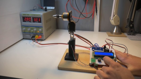
RC Boat Goes Brushless For Speed & Reliability

Remote control boats can be great fun, and come in all manner of forms. There are unpowered sailcraft, speedboats that scream under the power of internal combustion, and of course, those that move under electric power. The brushless motor revolution of the past 20 years in particular has proven capable of creating some exciting RC watercraft, and [Matt K] decided he wanted to get on board.

[Matt] had owned a Kyosho Jetstream 1000 for several years, but found the nitro engine to be temperamental and not the most fun for high-jinx down at the lake. An old-school brushed motor setup with mechanical speed control similarly failed to excite. However, after experiencing the power of brushless in RC planes, [Matt] knew what he had to do.

Using an online calculator, [Matt] determined that his earlier nitro powerplant was putting out roughly 900 watts. When it came to going brushless, he decided to spec a Turnigy powerplant with twice as much power, along with the requisite speed controller. There was some work to do to integrate the new motor with the original propeller driveshaft and water cooling system, but in the end [Matt] ended up with a much faster boat that is a lot less hassle to set up and run.

Perhaps though, your RC boat needs brains, over brawn? Perhaps it’s time to look at autonomy…

Video after the break.

Continue reading “RC Boat Goes Brushless For Speed & Reliability”

Friday Hack Chat: Motors Made Out Of PCBs

One of the most amazing technological advances found in this year’s Hackaday Prize is the careful application of copper traces turned into coils. We’ve seen this before for RFID tags and scanners, but we’ve never seen anything like what Carl is doing. He’s building brushless motors on PCBs.

All you need to build a brushless motor is a rotor loaded up with super powerful and very cheap magnets, and a few coils of wire. Now that PCBs are so cheap, the coils of wire are easily taken care of. A 3D printer and some eBay magnets finish off the rest. For this week’s Hack Chat, we’re talking with Carl about PCB motors.

Carl Bugeja is a 23-year old electronics engineer who is trying to design new robotics technology. His PCB Motor design won the Open Hardware Design Challenge and will be going to the Finals of the Hackaday Prize. This open-source PCB motor is a smaller, cheaper, and easier to assemble micro-brushless motor.

[Carl]’s main project, the PCB Motor is a stator that is printed on a 4-layer PCB board. The six stator poles are spiral traces wound in a star configuration. Although these coils produce less torque compared to an iron core stator, the motor is still suitable for high-speed applications. [Carl]’s been working on other PCB motor designs, like the Linear PCB motor which is a monorail on a PCB and the Flexible PCB actuator where the coils of wire are tucked inside Kapton.

During this Hack Chat, we’re going to be discussing:

  • The design and construction of brushless motors
  • How to drive these motors
  • PCB applications beyond standard circuitry
  • Building accessible robotics technology

You are, of course, encouraged to add your own questions to the discussion. You can do that by leaving a comment on the Hack Chat Event Page and we’ll put that in the queue for the Hack Chat discussion.join-hack-chat

Our Hack Chats are live community events on the Hackaday.io Hack Chat group messaging. This week is just like any other, and we’ll be gathering ’round our video terminals at noon, Pacific, on Friday, August 10th. Need a countdown timer? You wouldn’t if we switched to universal metric time.

Click that speech bubble to the right, and you’ll be taken directly to the Hack Chat group on Hackaday.io.

You don’t have to wait until Friday; join whenever you want and you can see what the community is talking about.

Flat Pack Generators

We just wrapped up the Power Harvesting challenge in the Hackaday Prize, and with that comes some solutions to getting power in some very remote places. [Vijay]’s project is one of the best, because his project is getting power in Antarctica. This is a difficult environment: you don’t have the sun for a significant part of the year, it’s cold, and you need to actually get your equipment down to the continent. [Vijay]’s solution was to use one of Antarctica’s greatest resources — wind — in an ingenious flat pack wind turbine.

There are a few problems to harvesting wind power in a barren environment. The first idea was to take a standard, off-the-shelf motor and attach some blades, but [Vijay] found there was too much detent torque, and the motor would be too big anyway.

The solution to this problem was to wind his own motor that didn’t have the problems of off-the-shelf brushless motors. The design that [Vijay] settled on is a dual axial flux generator, or a motor with a fixed stator with magnets and two rotors loaded up with copper windings. Think of it as a flattened, inverted version of the motor on your drone.

One interesting aspect of this design is that it takes up significantly less space than a traditional motor, while still being able to output about 100 Watts with the wind blowing. Add in some gearing to get the speed of the rotor right, and you have a simple wind generator that can be set up in minutes and carried anywhere. It’s a great project, and we’re glad to see this make it into the finals of The Hackaday Prize.

A 3D-Printed Robot Actuator

Somehow, walking robots at our level never really seem to deliver on the promise that should be delivered by all those legs. Articulation using hobby servos is simple enough to achieve, but cumbersome, slow, and not very powerful. [Paul Gould] has a plan to make a better, 3D-printed articulated robot actuator.

His solution is both novel and elegant, a fairly conventional arm geometry that has at its joints a set of brushless motors similar to but a little larger than the kind you might be more familiar with on multirotors, paired with 3D-printed cycloidal gearboxes. Magnetic encoders provide the necessary positional feedback, and the result is a unit that is both compact and powerful.

With such a range of small brushless motor controllers on the market, it’s at first sight unexpected that he’s designed his own controller board. But this gives him complete control over his software, plus the CAN bus that ties everything together. He’s given us a video which we’ve placed below the break, showing the build process, the impressive capabilities of his system, and a selection of builds including a robot dog complete with tail. This is definitely a project to watch.

Continue reading “A 3D-Printed Robot Actuator”

3000W Unicycle’s Only Limitation Is “Personal Courage”

Electric vehicles are fertile ground for innovation because the availability of suitable motors, controllers, and power sources makes experimentation accessible even to hobbyists. Even so, [John Dingley] has been working on such vehicles since about 2009, and his latest self-balancing electric unicycle really raises the bar by multiple notches. It sports a monstrous 3000 Watt brushless hub motor intended for an electric motorcycle, and [John] was able to add numerous touches such as voice feedback and 1950’s styling using surplus aircraft and motorcycle parts. To steer, the frame changes shape slightly with help of the handlebars to allow the driver’s center of gravity to shift towards one or the other outer rims of the wheel. In a test drive at a deserted beach, [John] tells us that the bike never went above 20% power; the device’s limitations are entirely by personal courage. Watch the video of the test, embedded below.

Continue reading “3000W Unicycle’s Only Limitation Is “Personal Courage””

Watch This Tiny Dome Auto-open And Close Into A Propeller

Careful planning and simulation is invaluable, but it can also be rewarding to dive directly into prototyping. This is the approach [Carl Bugeja] took with his Spherical Folding Propeller design which he has entered into the Open Hardware Design Challenge category of The 2018 Hackaday Prize. While at rest, the folding propeller looks like a small dome attached to the top of a motor. As the motor fires up, centrifugal forces cause the two main halves of the dome to unfold outward where they act as propeller blades. When the motor stops, the assembly snaps shut again.

[Carl] has done some initial tests with his first prototype attached to a digital scale as a way of measuring thrust. The test unit isn’t large — the dome is only 1.6 cm in diameter when folded — but he feels the results are promising considering the small size of the props and the fact that no simulation work was done during the initial design. [Carl] is looking to optimize the actual thrust that can be delivered, now that it has been shown that his idea of a folding dome works as imagined.

Going straight to physical prototyping with an idea can be a valid approach to early development, especially nowadays when high quality components and technologies are easily available even to hobbyists. Plus it can be great fun! You can see and hear [Carl]’s prototype in the short video embedded below.

Continue reading “Watch This Tiny Dome Auto-open And Close Into A Propeller”

Analyzing Hobby Motors With An Oscilloscope

We always like finding new excuses reasons to use our test equipment, so we couldn’t help but be intrigued by this tip from [Joe Mosfet]. He uses the ever-popular Rigol DS1054Z to demonstrate the differences between a handful of brushless motors when rotated by his handheld drill at a constant RPM. Not only is he able to identify a blown motor, but it allows him to visualize their specifications which can otherwise seem a bit mystifying.

One wire from each motor is used as the ground, and channels one and two are connected to the remaining wires. Despite the DS1054Z having four channels, [Joe] is actually only using two of them here. The third channel being displayed is a virtual channel created by a math function on the scope.

After wiring them up, each motor got put into the chuck of his drill and spun up to 1430 RPM. The resulting waveforms were captured, and [Joe] walks us through each one explaining what we’re seeing on the scope.

The bad motor is easy to identify: the phases are out of alignment and in general the output looks erratic. Between the good motors, the higher the Kv rating of the motor, the lower voltage is seen on the scope. That’s because Kv in the context of brushless motors is a measurement of how fast the motor will spin for each volt. The inverse is also true, and [Joe] explains that if he could spin his 2450Kv motor at exactly 2450 RPM, we should see one volt output.

Beyond demonstrating the practical side of Kv ratings, [Joe] also theorizes that the shape of the wave might offer a glimpse into the quality of the motor’s construction. He notes his higher end motors generate a nice clean sine wave, while his cheaper ones show distortion at the peaks. An interesting note, though he does stress he can’t confirm there’s a real-world performance impact.

Last year we featured a similar method for identifying bad brushless motors using a drill press and an oscilloscope, but we liked that [Joe] went through the trouble of testing multiple motors and explaining the differences in their output.

[via /r/multicopter]