Anyone who has ever wound a coil by hand has probably idly wondered “How do they do this with a machine?” at some point in the tedious process. That’s about when your attention wanders and the wire does what physics wants it to do, with the rat’s nest and cursing as a predictable result.
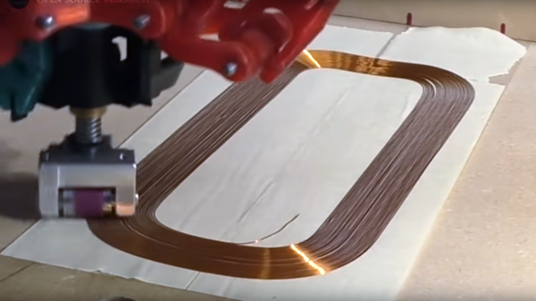
There’s got to be a better way, and [Russ Gries] is on his way to finding it with this proof-of-concept CNC flat coil winder. The video below is a brief overview of what came out of an intensive rapid prototyping session. [Russ] originally thought that moving the coil would be the way to go, but a friend put him onto the idea of using his delta-style 3D-printer to dispense the wire. An attachment somewhat like a drag knife was built, but with a wire feed tube and a metal roller to press the wire down onto an adhesive surface. The wire feed assembly went through a few design iterations before he discovered that a silicone cover was needed for the roller for the wire to properly track, and that the wire spool needed to be fed with as little friction as possible. Fusion 360’s CAM features were used to design the tool paths that describe the coils. It seems quite effective, and watching it lay down neat lines of magnet wire is pretty mesmerizing.
We’ve seen a couple of cylindrical coil winding rigs before, but it looks like this is the first flat coil winder we’ve featured. We can’t help but wonder about the applications. Wireless power transfer comes to mind, as do antennas and coils for RF applications. We also wonder if there are ways to use this to make printed circuit boards. Continue reading “Delta Printer Morphs Into CNC Flat Coil Winder”


 [Alan] was inspired to build
 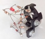 And you thought the autorouter in Eagle was bad.
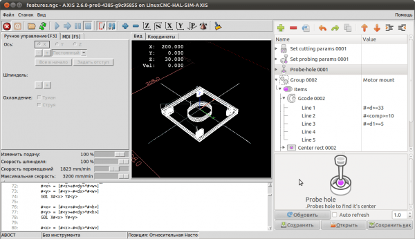
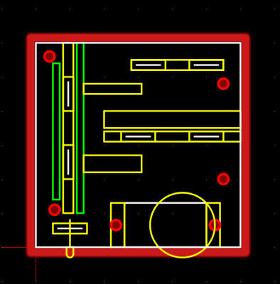 Not satisfied with the existing free and open source CAM programs,