Most photographs are made in the fraction of a second that the camera’s shutter is gathering reflected light from the scene. But there’s fun to be had by leaving the shutter open and directing light into the camera. Called light painting, it can be as simple as a camera on a tripod in a dark room and a penlight spelling out dirty words – not like we’d know – or as complicated as this CNC dot-matrix light printer.
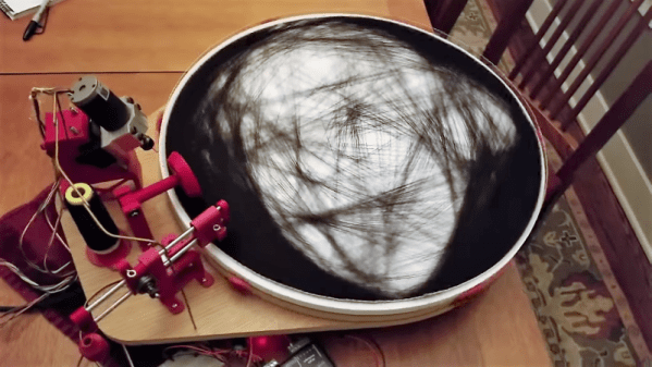
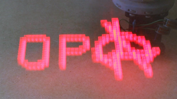
The first idea that [Jeremy S. Cook] had for this build didn’t go so well. He fitted an LED to the gantry of his 3D-printer, intending to send it G-code representing bitmaps. The idea would be to set it up in a dark place, open the shutter, and let the machine build up the image by rastering through the X- and Y- axes while blinking the LED on and off at the right time. But since the gantry only moves in one axis, he abandoned the printer in favor of his CNC router. He printed a collar to fit the dust collector shroud we previously featured, added a battery-powered LED, and affixed a pushbutton switch to the let the Z-axis turn on the light. It took some tweaking such as adding a translucent PLA diffuser, to get decent images, but in the end it worked. We like the soft look of the floating voxels, which were really helped by the later addition of a Nano and a Neopixel. Check out the build in the video below.
One thing we’d suggest is better reflection control. [Jeremy] used a black platen as a background, but it wasn’t quite enough. We suggest going none more black next time.