Low-Cost Cryocooler Pumps Out Cheap DIY Liquid Nitrogen

A word of caution if you’re planning to try this cryocooler method for making liquid nitrogen: not only does it involve toxic and flammable gasses and pressures high enough to turn the works into a bomb, but you’re likely to deplete your rent account with money you’ll shell out for all the copper tubing and fittings. You’ve been warned.

In theory, making liquid nitrogen should be as easy as getting something cold enough that nitrogen in the air condenses. The “cold enough” part is the trick, and it’s where [Hyperspace Pirate]’s cryocooler expertise comes into play. His setup uses recycled compressors from cast-off air conditioners and relies on a mixed-gas Joule-Thomson cycle. He plays with several mixtures of propane, ethylene, methane, argon, and nitrogen, with the best results coming from argon and propane in a 70:30 percent ratio. A regenerative counterflow heat exchanger, where the cooled expanding gas flows over the incoming compressed gas to cool it, does most of the heavy lifting here, and is bolstered by a separate compressor that pre-cools the gas mixture to about -30°C before it enters the regenerative system.

There’s also a third compressor system that pre-cools the nitrogen process gas, which is currently supplied by a tank but will eventually be pulled right from thin air by a pressure swing adsorption system — basically an oxygen concentrator where you keep the nitrogen instead of the oxygen. There are a ton of complications in the finished system, including doodads like oil separators and needle valves to control the flow of liquid nitrogen, plus an Arduino to monitor and control the cycle. It works well enough to produce fun amounts of LN2 on the cheap — about a quarter of the cost of commercially made stuff — with the promise of efficiency gains to come.

It does need to be said that there’s ample room for peril here, especially containing high pressures within copper plumbing. Confidence in one’s brazing skills is a must here, as is proper hydro testing of components. That said, [Hyperspace Pirate] has done some interesting work here, not least of which is keeping expenses for the cryocooler to a minimum.

Continue reading “Low-Cost Cryocooler Pumps Out Cheap DIY Liquid Nitrogen”

Low-Cost Electret Microphone Preamplifiers

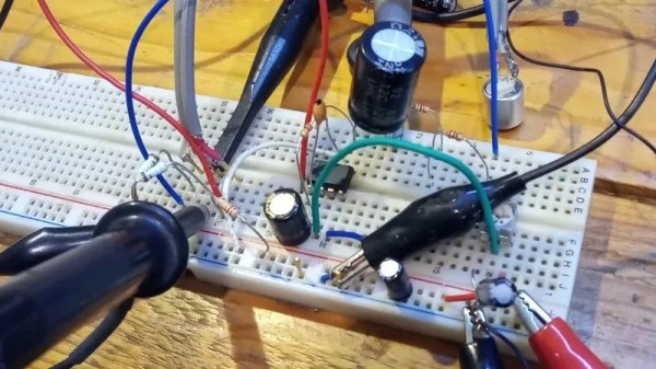
Before the invention of microelectromechanical system (MEMS) microphones, almost all microphones in cell phones and other electronics were a type of condenser microphone called the electret microphone. The fact that this type of microphone is cheap and easy enough to place into consumer electronics doesn’t mean they’re all low quality, though. Electret microphones can have a number of qualities that make them desirable for use recording speech or music, so if you have a struggling artist friend like [fvfilippetti] has who needs an inexpensive way to bring one to life, take a look at this electret microphone pre-amp.

The main goal of the project is to enhance the performance of these microphones specifically in high sound pressure level (SPL) scenarios. In these situations issues of saturation and distortion often occur. The preampl design incorporates feedback loops and an AD797 opamp to reduce distortion, increase gain, and maintain low noise levels. It also includes an output voltage limiter using diodes to protect against input overload and can adjust gain. The circuit’s topology is designed to minimize distortion, particularly in these high SPL situations.

Real-world testing of the preamp confirms its ability to handle high SPL and deliver low distortion, making it a cost-effective solution for improving the performance of electret microphones like these. If you want to go even deeper into the weeds of designing and building electret microphones and their supporting circuitry, take a look at this build which discusses some other design considerations for these types of devices.

History Of The Capacitor – The Modern Era

The pioneering years in the history of capacitors was a time when capacitors were used primarily for gaining an early understanding of electricity, predating the discovery even of the electron. It was also a time for doing parlor demonstrations, such as having a line of people holding hands and discharging a capacitor through them. The modern era of capacitors begins in the late 1800s with the dawning of the age of the practical application of electricity, requiring reliable capacitors with specific properties.

Leyden Jars

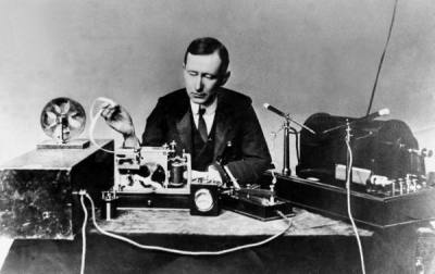
Marconi with transmitting apparatus
Marconi with transmitting apparatus, Published on LIFE [Public domain], via Wikimedia Commons
One such practical use was in Marconi’s wireless spark-gap transmitters starting just before 1900 and into the first and second decade. The transmitters built up a high voltage for discharging across a spark gap and so used porcelain capacitors to withstand that voltage. High frequency was also required. These were basically Leyden jars and to get the required capacitances took a lot of space.

Mica

In 1909, William Dubilier invented smaller mica capacitors which were then used on the receiving side for the resonant circuits in wireless hardware.

Early mica capacitors were basically layers of mica and copper foils clamped together as what were called “clamped mica capacitors”. These capacitors weren’t very reliable though. Being just mica sheets pressed against metal foils, there were air gaps between the mica and foils. Those gap allowed for oxidation and corrosion, and meant that the distance between plates was subject to change, altering the capacitance.

In the 1920s silver mica capacitors were developed, ones where the mica is coated on both sides with the metal, eliminating the air gaps. With a thin metal coating instead of thicker foils, the capacitors could also be made smaller. These were very reliable. Of course we didn’t stop there. The modern era of capacitors has been marked by one breakthrough after another for a fascinating story. Let’s take a look.

Continue reading “History Of The Capacitor – The Modern Era”

History Of The Capacitor – The Pioneering Years

The history of capacitors starts in the pioneering days of electricity. I liken it to the pioneering days of aviation when you made your own planes out of wood and canvas and struggled to leap into the air, not understanding enough about aerodynamics to know how to stay there. Electricity had a similar period. At the time of the discovery of the capacitor our understanding was so primitive that electricity was thought to be a fluid and that it came in two forms, vitreous electricity and resinous electricity. As you’ll see below, it was during the capacitor’s early years that all this changed.

The history starts in 1745. At the time, one way of generating electricity was to use a friction machine. This consisted of a glass globe rotated at a few hundred RPM while you stroked it with the palms of your hands. This generated electricity on the glass which could then be discharged. Today we call the effect taking place the triboelectric effect, which you can see demonstrated here powering an LCD screen.

Continue reading “History Of The Capacitor – The Pioneering Years”

A Simple FM Transmitter

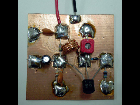
Here is a low component count FM transmitter. It sacrifices some features, like the ability to adjust the frequency, for simplicity’s sake. The build method is fairly common with amateur radio but we don’t see it around here too much. Each component gets a 5mm-by-5mm copper clad pad which is super glued to the ground plate as an insulator. There’s even a pictorial example of this method if you need some help with visualization.

One of the schematics included in the article shows how to incorporate a condenser microphone into the unit. We guess that makes it pretty easy to add an FM ‘bug’ to your arsenal of covert listening devices. Just make sure to check your local laws before building and using this. We’re not sure what the FCC would think of it here in America so we’re hoping some well-informed readers will educate us with a comment.

[Thanks Bart]

Condenser Microphone Building

mic

Browsing around today, this project caught our eye. Mainly due to the visual similarity to, well, personal massagers. As it turns out, it’s a home made studio condenser microphone. We would generally prefer to link directly to his personal page, that has a slightly more in dept write up, but it has popups and pop unders, so enter at your own risk.  Generally condenser mics require phantom power to make the magic happen, but he has included a circuit to run them off of 9v batteries. We’ve done condenser mics before, but this seems a bit quicker and dirtier.