Get Really Basic With Steppers And Eight Buttons

[Kevin Darrah] put together a good video showing how to control a stepper motor with, not a motor driver, but our fingers. Taking the really low-level approach to do this sort of thing gave us a much better understanding about the features of our stepper driver chips. Such as, for example, why a half step needed twice the current to operate.

[Kevin] starts with the standard explanation of coils, transistors, and magnets that every stepper tutorial does. When he hooks up simple breadboard with passives and buttons, and then begins to activate the switches in sequence is when we had our, “oh,” moment. At first even he has trouble remembering the correct sequence, but the stepper control became intuitive when laid out with tactile switches.

We set-up our own experiment to see if we remembered our lessons on the subject. It was a fun way to review what we already knew, and we learned some more along the way. Video after the break.

Continue reading “Get Really Basic With Steppers And Eight Buttons”

Control Your HTPC With Scavenged IR Parts

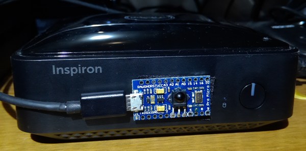
If you’ve built yourself a home theater PC, one of your highest priorities is probably coming up with a convenient control solution. The easiest way to do this is to simply use something like a wireless keyboard and mouse. But, that’s not very conducive to an enjoyable home theater experience, and it feels pretty clunky. However, if you’ve got the right components lying around, [Sebastian Goscik] has instructions and an Arduino sketch that will let you control your HTPC with any IR remote control.

There are a number of ways you could control your HTPC, and we’ve featured more than one build specifically for controlling XBMC over the years. Unfortunately, most of those methods require that you spend your hard earned money (which is better spent on popcorn). [Sebastian’s] setup can be replicated with things you probably have on hand: an Arduino, an IR remote, and a scavenged IR receiver. The IR receiver can be found in many devices, like old stereos or TVs that themselves were controlled via an IR remote.

It starts with an Arduino Sketch that lets you can see on the serial monitor what code is being generated by the button presses on your remote. These are then scripted to perform any task or function you like when those buttons are pushed. The most obvious use here is simple directional control for selecting your movies, but much more complex tasks are possible. Maybe someone can program a T9 script to type using the number buttons on most remotes?

Cat Feeder

Hack Your Cat’s Brain To Hunt For Food

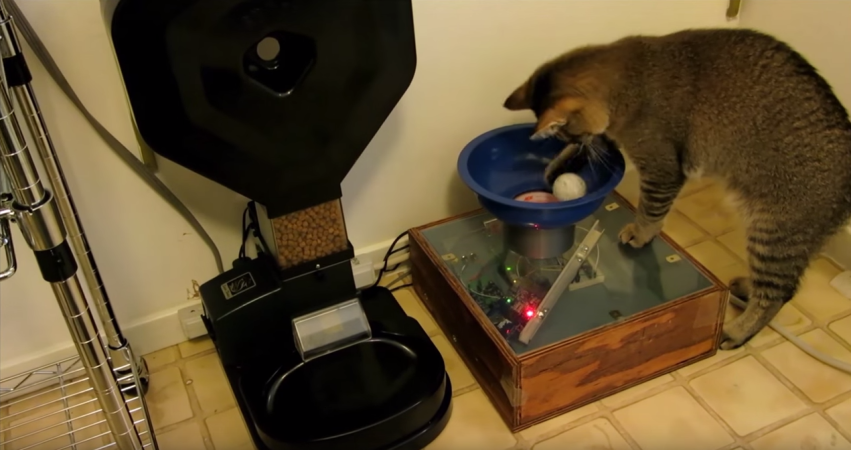
This cat feeder project by [Ben Millam] is fascinating. It all started when he read about a possible explanation for why house cats seem to needlessly explore the same areas around the home. One possibility is that the cat is practicing its mobile hunting skills. The cat is sniffing around, hoping to startle its prey and catch something for dinner. Unfortunately, house cats don’t often get to fulfill this primal desire. [Ben] thought about this problem and came up with a very interesting solution. One that involves hacking an electronic cat feeder, and also hacking his cat’s brain.

First thing’s first. Click past the break to take a look at the demo video and watch [Ben’s] cat hunt for prey. Then watch in amazement as the cat carries its bounty back to the cat feeder to exchange it for some real food.

Continue reading “Hack Your Cat’s Brain To Hunt For Food”

Walk Your Pet Robot

Anyone who’s ever tried to build a bipedal robot will quickly start pulling their own hair out. There are usually a lot of servos involved, and controlling them all in a cohesive way is frustrating to say the least. [Mark] had this problem while trying to get his robot to dance, and to solve it he built a control system for a simple bipedal robot that helps solve this problem.

[Mark]’s robot has six servo motors per leg, for a total of 12 degrees of freedom. Commands are sent to the robot with an RC radio, and the control board that he built, called the Smart Servo Controller, receives the signals and controls the servos appropriately. There are 14 outputs for servos, operating at 12 bits and 50 Hz each, as well as 8 input channels. The servo controller can be programmed on a computer with user-selectable curves for various behaviors for each of the servos on the project. This eliminates the need to write cumbersome programs for simple robot movements, and it looks like it does a pretty good job!

Full disclosure: [Mark] currently has this project up on Kickstarter, but it is a unique take on complex robot control that could help out in a lot of different ways. Since you don’t need to code anything, it could lower the entry barrier for this type of project, possibly opening it up to kids or school projects. Beyond that, even veterans of these types of projects could benefit by not having to do as much brute-force work to get their creations up and moving around!

Continue reading “Walk Your Pet Robot”

Remote Tester

A Simple Circuit For Testing Infrared Remote Controls

Every now and then a remote control acts up. Maybe you are trying to change the channel on your television and it’s just not working. A quick way to determine if the remote control is still working is by using a cell phone camera to try to see if the IR LED is still lighting up. That can work sometimes but not always. [Rui] had this problem and he decided to build his own circuit to make it easier to tell if a remote control was having problems.

The circuit uses a Vishay V34836 infrared receiver to pick up the invisible signals that are sent from a remote control. A Microchip 12F683 processes the data and has two main output modes. If the remote control is receiving data continuously, then a green LED lights up to indicate that the remote is functioning properly. If some data is received but not in a continuous stream, then a yellow LED lights up instead. This indicates that the batteries on the remote need to be replaced.

The circuit also includes a red LED as a power indicator as well as RS232 output of the actual received data. The PCB was cut using a milling machine. It’s glued to the top of a dual AAA battery holder, which provides plenty of current to run the circuit.

Beach Sign

LED Sign Brightens Up The Beach After Dark

[Warrior_Rocker’s] family bought a fancy new sign for their beach house. The sign has the word “BEACH” spelled vertically. It originally came with blue LEDs to light up each letter. The problem was that the LEDs had a narrow beam that would blind people on the other side of the room. Also, there was no way to change the color of the LEDs, which would increase the fun factor. That’s why [Warrior] decided to upgrade the sign with multi-colored LEDs.

After removing the cardboard backing of the sign, [Warrior] removed the original LEDs by gently tapping on a stick with a hammer. He decided to use WS2811 LED pixels to replace the original LEDs. These pixel modules support multiple colors and are individually addressable. This would allow for a wide variety of colors and animations. The pixels came covered in a weatherproof resin material. [Warrior] baked the resin with a heat gun until it became brittle. He was then able to remove it entirely using some pliers and a utility knife. Finally, the pixels were held in place with some hot glue.

Rather then build a remote control from scratch, [Warrior] found a compatible RF remote under ten dollars. The LED controller was removed from its housing and soldered to the string of LEDs. It was then hot glued to a piece of cardboard and placed into the sign’s original battery compartment. Check out the video below for a demonstration. Continue reading “LED Sign Brightens Up The Beach After Dark”

Balancing A Ball With A Solar Cell

Go to any control systems class, and you’ll see a final project that demonstrates loops, integration, and everything else that can be learned in a semester or two of control theory. This project is not from one of those classes. It is, however, very cool: it balances a 40mm steel ball on the rim of a lasercut wood wheel using nothing more than a solar cell as a sensor.

[Manuel] was inspired to build this ball-balancing device after seeing a similar project at CCC about six years ago. He doesn’t remember who made it, and eschewed the PC/Matlab architecture of the original, but this build retains one interesting feature of its muse. The input to the control system is just a high intensity light bulb and a solar cell. The 40mm steel ball blocks the light reaching the solar cell most of the time. Slight variations in voltage go through the control system to keep this ball balanced on top of the wheel.

The only hardware for this build is a motor, a motor driver, and an ATMega644P. The first revision of the hardware was just a few breakout boards stuffed into a rat’s nest of wiring in the base of the build, but this has been fixed in version two with a new PCB. Video below.

Continue reading “Balancing A Ball With A Solar Cell”