Wireless Earbuds Charge Themselves

As more and more ports are removed from our smart devices, it seems that we have one of two options available for using peripherals: either buy a dongle to continue to use wired devices, or switch to Bluetooth and deal with perpetually maintaining batteries. If neither of these options suits you, though, there’s a third option available as [befinitiv] shows us in this build where he integrates a tiny solar panel to his earbud case to allow them to automatically charge themselves.

To start, he begins by taking apart the earbud case. For those who still haven’t tried out a set of these, they typically charge only when placed inside of their carrying case, which in his case also contains a small battery itself. Soldering wires directly to the battery allow for the battery to charge without as much electrical loss as he would have had if he had connected to the USB pins on the circuit board. Even then, the cell only generates a single volt so he needs a 5V boost converter to properly charge the battery. That came with its own problem, though, as it wouldn’t fit into the case properly. To solve that issue, he desoldered all of the components and deadbugged them together in order to fit the converter into a much smaller space without having to modify the case in any other way.

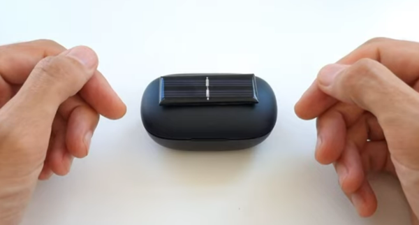
With all of that done and the small solar cell attached to the case, [befinitiv] has a smart solution to keep his wireless earbuds topped up without having to carry cables or dongles around every day. We’ve seen plenty of interesting solutions to the problem of various electronics manufacturers removing the ubiquitous 3.5 mm headphone jack too, and not all of them have dealt with this problem without certain other quirks arising as a result.

Continue reading “Wireless Earbuds Charge Themselves”

Bench Supplies Get Smaller Thanks To USB-C

Bench power supplies are an indispensable tool when prototyping electronics. Being able to set custom voltages and having some sort of current limiting feature are key to making sure that the smoke stays inside all of the parts. Buying a modern bench supply might be a little too expensive though, and converting an ATX power supply can be janky and unreliable. Thanks to the miracle of USB-C, though, you can build your own fully-featured benchtop power supply like [Brian] did without taking up hardly any space, and for only around $12.

USB-C can be used to deliver up to 100W but is limited to a few set voltage levels. For voltages that USB-C doesn’t support, [Brian] turns to an inexpensive ZK-4KX buck-boost DC-DC converter that allows for millivolt-level precision for his supply’s output. Another key aspect of using USB-C is making sure that your power supply can correctly negotiate for the amount of power that it needs. There’s an electronic handshake that goes on over the USB connection, and without it there’s not a useful amount of power that can be delivered. This build includes a small chip for performing this negotiation as well.

With all the electronics taken care of, [Brian] houses all of this in a 3D-printed enclosure complete with a set of banana plugs. While it may not be able to provide the wattage of a modern production unit, for most smaller use cases this would work perfectly. If you already have an ATX supply around, though, you can modify [Brian]’s build using that as the supply and case too.

Continue reading “Bench Supplies Get Smaller Thanks To USB-C”

A Simple Soft Power Switch Using Common Modules

If you want to easily control the power in a circuit, you’ll probably reach for the classic toggle switch. While there’s certainly nothing wrong with that, physical toggles are a bit dated at this point. A soft power switch that turns your gadget on and off at the tap of a finger is far more 21st century. You might think this kind of modern trickery is too difficult to implement on a DIY project, but as [Sasa Karanovic] shows, it’s actually a lot easier than you might think.

Now to be fair, that wasn’t actually his goal. All [Sasa] was trying to do was come up with a slick way to control the LED lighting in his 3D printer enclosure. Which, as you can see in the video below, he accomplished. But the hacked together circuit he used to do it could easily be adapted for other electronic projects. If you’re using a LM2596 DC-DC converter module to power your gadget, you can add a touch sensitive soft switch for literally pennies.

The trick is utilizing the enable pin on the LM2596. The common buck converter modules tie this pin to ground so the regulator is always enabled, but if you lift the pin off the PCB and connect it to the output of a TTP223 capacitive touch sensor, you can simply tap the pad to control the regulator. Power for the touch sensor itself is pulled from the input side of the regulator, so even when the power is cut off downstream, the sensor is still awake and can kick the chip back into gear when you need it.

If you’re not interested in touch control, you could try connecting the enable pin on the regulator to an ESP8266 and making a cheap Internet-controlled DC power supply. Continue reading “A Simple Soft Power Switch Using Common Modules”

DIY Magsafe Charger Feeds Off 12 V Solar Battery

[Steve Chamberlin] has a spiffy solar-charged 12 V battery that he was eager to use to power his laptop, but ran into a glitch. His MacBook Pro uses Apple’s MagSafe 2 connector for power, but plugging the AC adapter into the battery via a 110 VAC inverter seemed awfully inefficient. It would be much better to plug it into the battery directly, but that also was a problem. While Apple has a number of DC power adapters intended for automotive use, none exist for the MagSafe 2 connector [Steve]’s mid-2014 MacBook Pro uses. His solution was to roll his own MagSafe charger with 12 VDC input.

Since MagSafe connectors are proprietary, his first duty was to salvage one from a broken wall charger. After cleaning up the wires and repairing any frayed bits, it was time to choose a DC-DC converter to go between the MagSafe connector and the battery. The battery is nominally 12 volts, so the input of the DC-DC converter was easy to choose, but the output was a bit uncertain. Figuring out what the MagSafe connector expects took a little educated guesswork.

The original AC adapter attached to the charger claimed an output of 20 volts, another Apple adapter claimed a 14.85 V output, and a third-party adapter said 16.5 volts. [Steve] figured that the MagSafe connectors seemed fine with anything in the 15 to 20 V range, so it would be acceptable to use a 12 V to 19 V DC-DC boost converter which he had available. The result worked just fine, and [Steve] took measurements to verify that it is in fact much more efficient than had he took the easy way out with the inverter.

MagSafe has been displaced by USB-C nowadays, but there are plenty of MagSafe devices still kicking around. In a pinch, keep in mind that a little bit of filing or grinding is all that’s needed to turn MagSafe 1 into MagSafe 2.

Bench Power Supply Packs A Lot Into A DIN-Rail Package

We’re not sure why we’ve got a thing for DIN-rail mounted projects, but we do. Perhaps it’s because we’ve seen so many cool industrial control cabinets, or maybe the forced neatness of DIN-mounted components resonates on some deep level. Whatever it is, if it’s DIN-rail mounted, chances are good that we’ll like it.

Take this DIN-mounted bench power supply, for instance. On the face of it, [TD-er]’s project is yet another bench supply built around those ubiquitous DPS switching power supply modules, the ones with the colorful displays. Simply throwing one of those in a DIN-mount enclosure isn’t much to write home about, but there’s more to this project than that. [TD-er] needed some fixed voltages in addition to the adjustable output, so a multi-voltage DC-DC converter board was included inside the case as well. The supply has 3.3, 5, and 12 volt fixed outputs along with the adjustable supply, and thanks to an enclosed Bluetooth module, the whole thing can be controlled from his phone. Plus it fits nicely in a compact work area, which is a nice feature.

We haven’t seen a lot of DIN-rail love around these pages — just this recent rotary phase converter with very tidy DIN-mounted controls. That’s a shame, we’d love to see more.

Hybrid Bench Power Supply Can Also Hit The Road

Everyone needs a bench power supply, and rolling your own has almost become a rite of passage for hackers. For a long time, the platform of choice for such builds seemed to be the ATX power supply from a computer. While we certainly still see those builds, a lot of the action has switched to those cheap eBay programmable DC-DC converters, with their particolored digital displays.

This hybrid bench and portable power supply is a good example of what can be accomplished with these modules, and looks like it might turn out to be a handy tool. [Luke] centered his build around the DPS3003, a constant current and constant voltage buck converter that can take up to 40-VDC input and outputs up to 32 volts at 3 amps. In bench mode, the programmable module is fed from a mains-powered 24-volt switching supply. For portable work, an 18-volt battery from a Makita drill slips into a 3D-printed adapter on the top of the case. The printed part contains a commercial terminal [Luke] scored on eBay, but we’d bet the entire thing could be 3D printed. And no problem if you change power tool brands — just print another adapter.

Those little eBay power supply modules have proven to be an enabling technology, at least judging by the number of clever ways we’ve seen them used lately. From this combination bench PSU and soldering iron supply to a portable PSU perched atop a battery, these things are everywhere. Heck, you can even reflash the firmware and make them do your bidding.

[via Dangerous Prototypes]

The Pros And Cons Of Microcontrollers For Boost Converters

It never fails — we post a somewhat simple project using a microcontroller and someone points out that it could have been accomplished better with a 555 timer or discrete transistors or even a couple of vacuum tubes. We welcome the critiques, of course; after all, thoughtful feedback is the point of the comment section. Sometimes the anti-Arduino crowd has a point, but as [Great Scott!] demonstrates with this microcontroller-less boost converter, other times it just makes sense to code your way out of a problem.

Built mainly as a comeback to naysayers on his original boost-converter circuit, which relied on an ATtiny85, [Great Scott!] had to go to considerable lengths to recreate what he did with ease using a microcontroller. He started with a quick demo using a MOSFET driver and a PWM signal from a function generator, which does the job of boosting the voltage, but lacks the feedback needed to control for varying loads.

Ironically relying on a block diagram for a commercial boost controller chip, which is probably the “right” tool for the job he put together the final circuit from a largish handful of components. Two op amps form the oscillator, another is used as a differential amp to monitor the output voltage, and the last one is a used as a comparator to create the PWM signal to control the MOSFET. It works, to be sure, but at the cost of a lot of effort, expense, and perf board real estate. What’s worse, there’s no simple path to adding functionality, like there would be for a microcontroller-based design.

Of course there are circuits where microcontrollers make no sense, but [Great Scott!] makes a good case for boost converters not being one of them if you insist on DIYing. If you’re behind on the basics of DC-DC converters, fear not — we’ve covered that before.

Continue reading “The Pros And Cons Of Microcontrollers For Boost Converters”