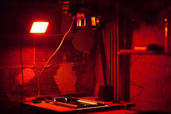
As the world becomes more and more digital, there are still a few holdouts from the analog world we’ve left behind. Vinyl records are making quite the comeback, and film photography is still hanging on as well. While records and a turntable have a low barrier for entry, photography is a little more involved, especially when developing the film. But with the right kind of equipment you can bridge the gap from digital to analog with a darkroom setup that takes digital photographs and converts them to analog prints.
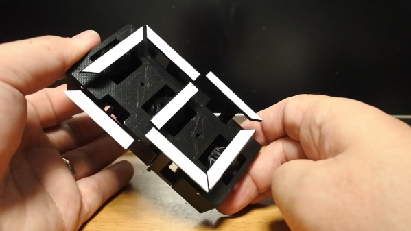
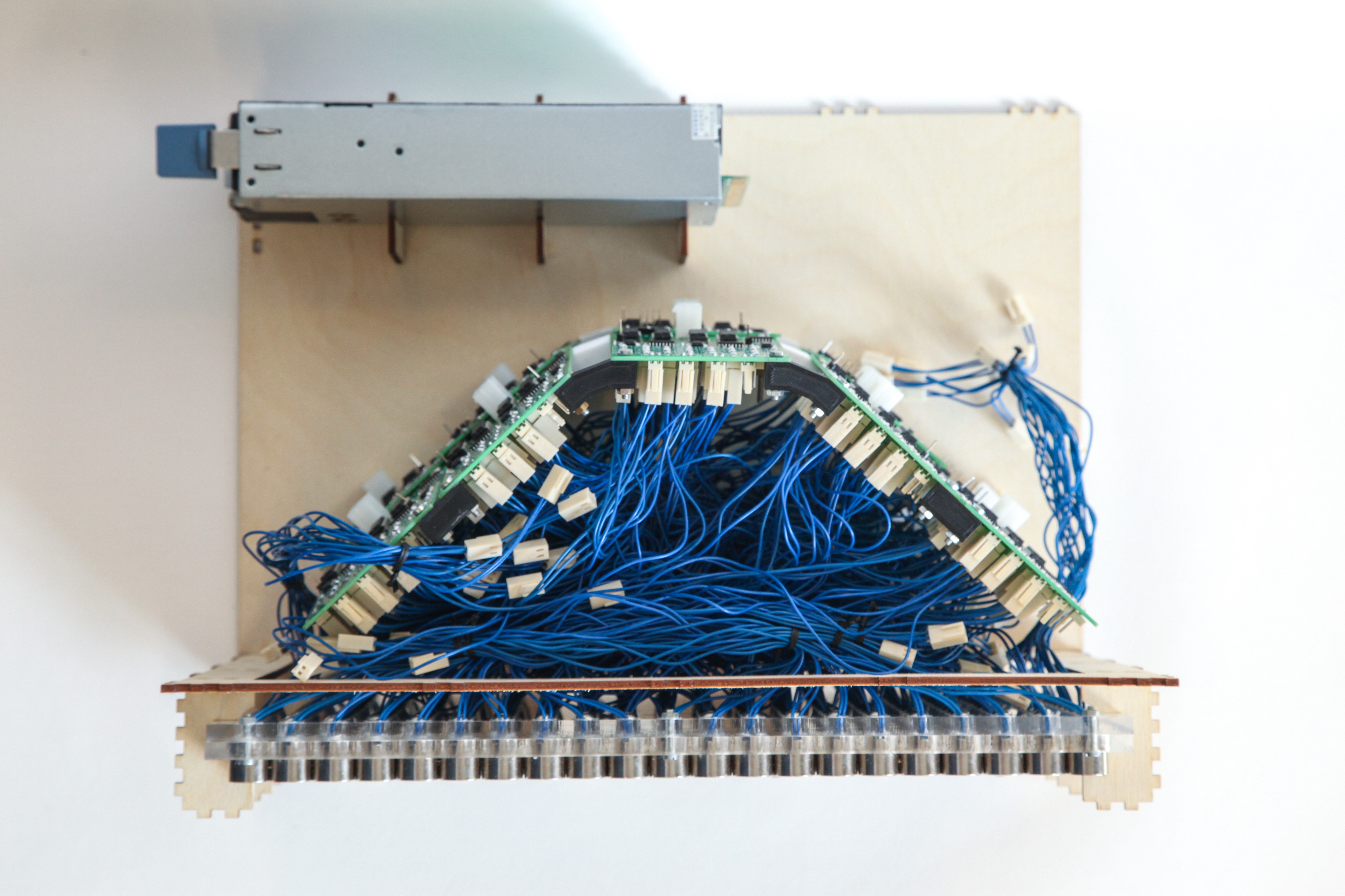
The project’s creator, [Muth], has been working on this project since he found a 4K monochrome display. These displays are often used in resin 3D printers, but he thought he could put them to use developing photographs. This is much different from traditional darkroom methods, though. The monochrome display is put into contact with photo-sensitive paper, and then exposed to light. Black pixels will block the light while white pixels allow it through, creating a digital-to-analog negative of sorts. With some calibration done to know exactly how long to expose each “pixel” of the paper, the device can create black-and-white analog images from a digital photograph.
[Muth] notes that this method isn’t quite as good as professional print, but we wouldn’t expect it to be. It creates excellent black-and-white prints with a unique method that we think generates striking results. The 4K displays needed to reproduce this method aren’t too hard to find, either, so it’s fairly accessible to those willing to build a small darkroom to experiment. For those willing to go further, take a look at some other darkroom builds we’ve seen in the past.