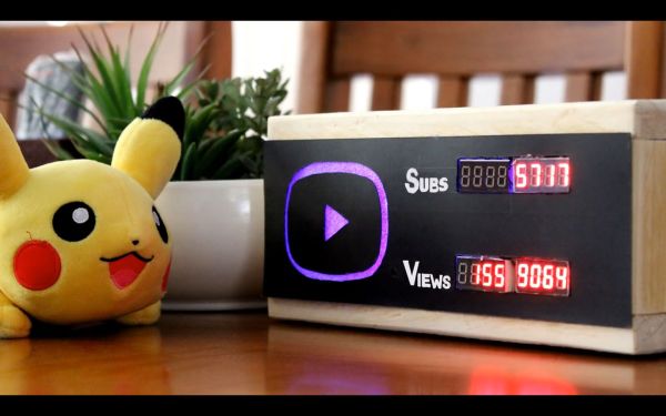
How do you hack your motivation? Do you put red marker Xs on a paper calendar every day you exercise? Do you use an egg timer to sprint through dozens of emails? Do you lock all the doors and shut off your data to write some bulletproof code? If you are [Hulk], you build a YouTube Desktop Notifier showing his YouTube subscribers and views. This is his ticket to getting off the couch to make a video about just such a device. There is something poetic about building a mechanism to monitor its own success making a feedback loop of sorts. The Hackaday.io page follows the video, so anyone who wants to build their own doesn’t have to scribble notes while pausing the video which is also posted below the break.
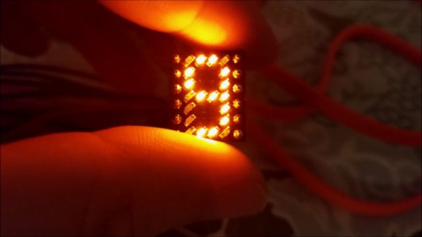
The hardware list is logical, starting with a NodeMCU module programmed through the Arduino IDE. Addressable 7-segment displays show the statistics in red, but you can sub in your preferred color with the back-lighting LEDs. It should be possible to share the CLK pins on the displays if you are important enough to need more digits. [Hulk] already outlined a list of improvements including switching to addressable backlights and adding daily and monthly tracking.
Monitoring online values without a computer monitor is satisfying on a level because it shows what motivates us, whether that is Bitcoin or the weather.