A Raspberry Pi Is A Hardware Hacker’s Swiss Army Knife

By now most of us have used a Raspberry Pi at some level or another. As a headless server it’s a great tool because of its price point, and as an interface to the outside world the GPIO pins are incredibly easy to access with a simple Python script. For anyone looking for guidance on using this device at a higher level, though, [Arun] recently created a how-to for using some of the Pi’s available communications protocols.

Intended to be a do-everything “poor man’s hardware hacking tool” as [Arun] claims, his instruction manual details all the ways that a Raspberry Pi can communicate with other devices using SPI and I2C, two of the most common methods of interacting with other hardware beyond simple relays. If you need to go deeper, the Pi can also be used as a full JTAG interface or SWD programmer for ARM chips. Naturally, UART serial is baked in. What more do you need?

As either a tool to keep in your toolbox for all the times you need to communicate with various pieces of hardware, or as a primer for understanding more intricate ways of using a Raspberry Pi to communicate with things like sensors or other computers, this is a great write-up. We also have more information about SPI if you’re curious as to how the protocol works.

Thanks to [Adrian] for the tip!

Pac-Man Fever Comes To The Pano Logic FPGA

If you’ve been reading Hackaday for a while now, you might recall the tale of Pano Logic that we first covered all the way back in 2013. They were a company that put out some very interesting FPGA-based thin clients, but as occasionally happens in situations like this, the market wasn’t ready and the company went belly up. These thin clients, now without official support, invariably got dumped onto the second-hand market. Shame for Pano Logic and their staff, but good news for hackers like [Skip Hansen].

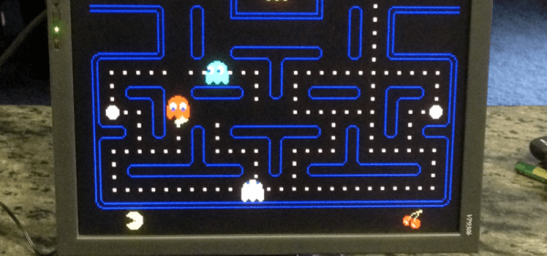
After seeing a few posts about the Pano Logic devices and general FPGA hacking, he decided to grab a few on eBay and dive in. Using open source tools and the wealth of information that’s available [Skip] was able to get a Pac-Man simulator up and running over his holiday break, and he tells us his life may never be the same again. FPGA hacking is a fascinating subject with a lot of activity right now, and since you can get these Pano Logic boxes on eBay for less than $10 USD in some cases, now is as good a time as ever to get your feet wet.

Like many open source projects, [Skip] says his code is built upon the existing work of a number of other programmers, which let him get up and running much faster than if he had to start from scratch. He describes his code as the “glue” that mashes these projects together, but we think he’s being somewhat modest there. It took more than copying and pasting some code into an IDE to get Blinky, Pinky, Inky and Clyde doing their thing on the Pano Logic.

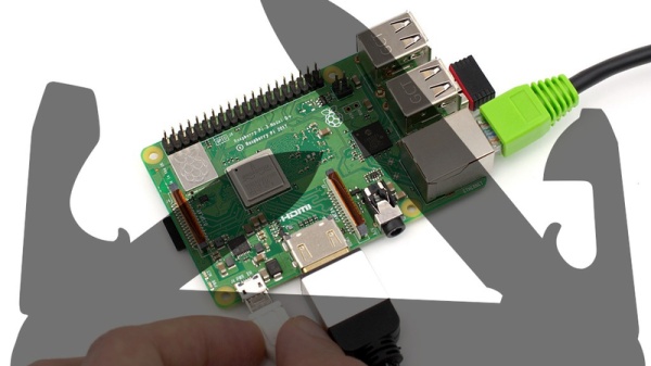
The biggest challenge was the lack of I/O. The Pano Logic thin clients have USB ports, but it seems nobody has quite figured out how to get them working yet. To talk to the outside world, you’ve got to get a little more creative. Eventually [Skip] was able to track down four lines he could effectively use as GPIO: two which are used to drive the LEDs on the device, and two which are used for the VGA port’s Display Data Channel (DDC) pins. Soldering jumpers from the LEDs to the unused pins in the device’s VGA connector meant he was even able to get these four GPIO lines accessible from the outside of the Pano Logic without having to cut any holes in the case.

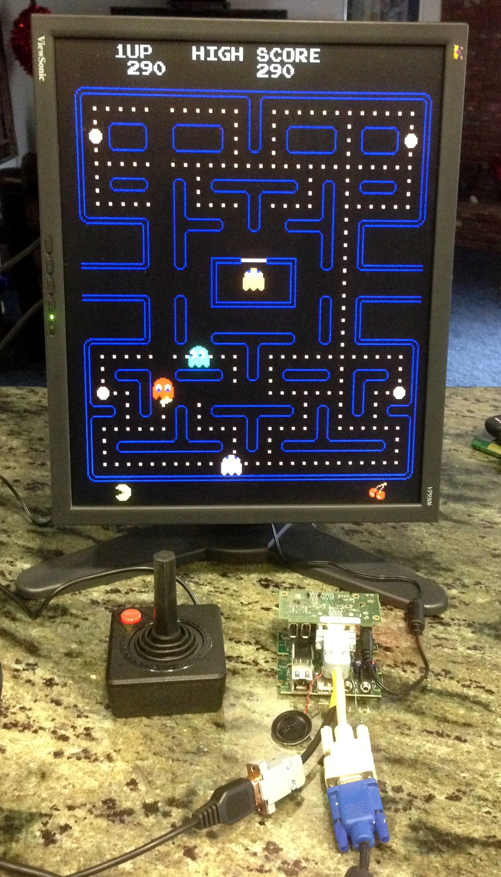
Anyone with a Pano Logic client that has a VGA port, an Atari 2600 joystick, and who doesn’t mind soldering a couple of wires can now play Pac-Man with the bitstream [Skip] has provided. But where do we go from here? How long until we see DOOM running on it? Perhaps one of you fine readers should pick one up and see what you can do to advance the state of Pano Logic hacking. Just be sure to let us know about it.

We’ve previously covered one of the projects used to get this Pac-Man simulator off the ground, a very cool ray tracing demo for the Pano Logic developed by [Tom Verbeure]. In fact, [Skip] says that project was what got him interested in FPGA hacking in the first place. If you’re thinking of following his lead, you might also want to check out our FPGA Boot Camp.

Arduino Gets A Command Line Interface

When using an Arduino, at least once you’ve made it past blinking LEDs, you might start making use of the serial connection to send and receive information from the microcontroller. Communicating with the board while it’s interacting with its environment is a crucial way to get information in real-time. Usually, that’s as far as it goes, but [Pieter] wanted to take it a step farther than that with his command line interpreter (CLI) for the Arduino.

The CLI allows the user to run Unix-like commands directly on the Arduino. This means control of GPIO and the rest of the features of the microcontroller via command line. The CLI communicates between the microcontroller and the ANSI/VT100 terminal emulator of your choosing on your computer, enabling a wealth of new methods of interacting with an Arduino.

The CLI requires a hex file to be loaded onto the Arduino that you can find at a separate site, also maintained by [Pieter]. Once that’s running, you can get all of that sweet command line goodness out of your Arduino. [Pieter] also has some examples on his project page, as well as the complete how-to to get this all set up and running. There’s a lot going on in the command line world, in Linux as well as windows. So there’s plenty to explore there as well.

Adding 3D Printer Power And Light Control To OctoPrint

OctoPrint is a great way to monitor your printer, especially with the addition of a webcam. Using a tablet or mobile phone, you can keep an eye on what the printer is doing from anywhere in the house (or world, if you take the proper precautions), saving you from having to sit with the printer as if it’s an infant. But simply watching your printer do its thing is only a small slice of the functionality offered by OctoPrint’s vast plugin community.

As [Jeremy S Cook] demonstrates, it’s fairly easy to add power control for the printer and auxiliary lighting to your OctoPrint setup. Being able to flick the lights on over the print bed is obviously a big help when monitoring it via webcam, and the ability to turn the printer off can provide some peace of mind after the print has completed. If you’re particularly brave it also means you could power on the printer and start a print completely remotely, but good luck if that first layer doesn’t go down perfectly.

In terms of hardware, you only need some 3.3V relays for the Raspberry Pi running OctoPrint to trigger, and an enclosure to put the wiring in. [Jeremy] uses only one relay in this setup to power the printer and lights at once, but with some adjustment to the software, you could get independent control if that’s something you’re after.

On the software side [Jeremy] is using an OctoPrint plugin called “PSU Control”, which is actually intended for controlling an ATX PSU from the Pi’s GPIO pins, but the principle is close enough to throw a relay. Other plugins exist which allow for controlling a wider away of devices and GPIO pins if you want to make a fully remote controlled enclosure. Plus you can always whip up your own OctoPrint plugin if you don’t find anything that quite meets your switching needs.

[Jeremy] previously documented his unique mount to keep his Raspberry Pi and camera pointed at his printer, which is naturally important if you want to create some cool videos with Octolapse.

Continue reading “Adding 3D Printer Power And Light Control To OctoPrint”

Save Some Steps With This Arduino Rapid Design Board

We’re all familiar with the wide variety of Arduino development boards available these days, and we see project after project wired up on a Nano or an Uno. Not that there’s anything wrong with that, of course, but there comes a point where some hobbyists want to move beyond plugging wires into header sockets and build the microcontroller right into their project. That’s when one generally learns that development boards do a lot more than break the microcontroller lines out to headers, and that rolling your own design means including all that supporting circuitry.

To make that transition easier, [Sean Hodgins] has come up with a simple Arduino-compatible module that can be soldered right to a PCB. Dubbed the “HCC Mod” for the plated half-circle castellations that allows for easy soldering, the module is based on the Atmel SAMD21 microcontroller. With 16 GPIO lines, six ADCs, an onboard 3.3 V regulator, and a reset button, the module has everything needed to get started — just design a PCB with the right pad layout, solder it on, and surround it with your circuitry. Programming is done in the familiar Arduino IDE so you can get up and running quickly. [Sean] has a Kickstarter going for the modules, but he’s also releasing it as open source so you’re free to solder up your own like he does in the video below.

It’s certainly not the first dev module that can be directly soldered to a PCB, but we like the design and can see how it would simplify designs. [Sean] as shown us a lot of builds before, like this army of neural net robots, so he’ll no doubt put these modules to good use.

Continue reading “Save Some Steps With This Arduino Rapid Design Board”

General Purpose I/O: How To Get More

The first program anyone writes for a microcontroller is the blinking LED which involves toggling a general-purpose input/output (GPIO) on and off. Consequently, the same GPIO can be used to read digital bits as well. A traditional microcontroller like the 8051 is available in DIP packages ranging from 20 pins to 40 pins. Some trade the number of GPIOs for compactness while other devices offer a larger number of GPIOs at the cost of complexity in fitting the part into your design. In this article, we take a quick look at applications that require a larger number of GPIOs and traditional solutions for the problem.

A GPIO is a generic pin on an integrated circuit or computer board whose behavior, including whether it is an input or output pin, is controllable by the user at runtime. See the internal diagram of the GPIO circuit for the ATmega328 for reference.

Simply put, each GPIO has a latch connected to a drive circuit with transistors for the output part and another latch for the input part. In the case of the ATmega328, there is a direction register as well, whereas, in the case of the 8051, the output register serves as the direction register where writing a 1 to it sets it in output mode.

The important thing to note here is that since all the circuits are on the same piece of silicon, the operations are relatively fast. Having all the latches and registers on the same bus means it takes just one instruction to write or read a byte from any GPIO register.
Continue reading “General Purpose I/O: How To Get More”

Pocket-size Pi Zero Desktop Features E-paper Display

[Ramin Assadollahi] uses his Raspberry Pi Zero W as a self-contained mobile desktop, connecting to it over VNC from another computer when he wants to hack away at some code or work on a new project. But he often found himself wishing there was some convenient way of displaying pertinent into right on the device, such as what IP address the Pi Zero had pulled. Then he found the 2.13 inch e-Paper HAT for the Pi Zero from Waveshare, and it all clicked into place.

The final device, which he refers to as the StickPi, combines a Pi Zero W, the Waveshare e-Paper display, and a strip of protoboard featuring a few tactile buttons, all inside of a 3D printed case. To really get the most out of the internal volume of his case, [Ramin] soldered the header pins to the Pi Zero in the middle, allowing him to create a space-saving “sandwich” out of all the components.

With the e-Paper display, [Ramin] now has a way to show information on the device itself without having to connect to it over the network. But thanks to the tactile switches on the back connected to the Pi’s GPIO, he also has six programmable buttons that could do anything he wants.

In the most basic implementation, each button could execute a command or script on the Pi. But [Ramin] has something a little more advanced in mind. In the video after the break, he explains that his next step is going to be working on an actual user interface for the Pi’s e-Paper screen, making use of the roughly gamepad style layout of the rear buttons. A “paged” interface with scrolling options would allow the user to perform all sorts of functions quickly and easily, and we’re looking forward to seeing what he comes up with.

This isn’t the first time we’ve seen somebody try to turn the Pi Zero into a more mobile-friendly platform, and the construction method here actually reminds us of a much smaller version of the Zero Phone.

Continue reading “Pocket-size Pi Zero Desktop Features E-paper Display”