Automatic Position Reporting Over HF Radio

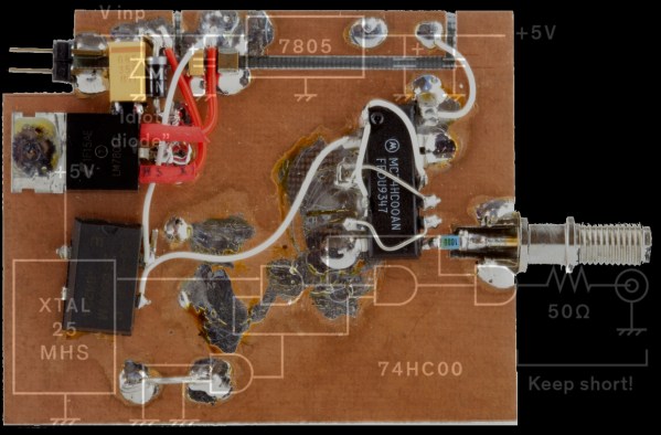
While most of us carry cell phones that have GPS and other location services, they require a significant amount of infrastructure to be useful. Drive from Washington to Alaska like [Lonney] did a while back, where that infrastructure is essentially nonexistent, and you’ll need to come up with some other solutions to let friends and family know where you are.

A tool called the Automatic Packet Reporting System (APRS) is fairly robust in the very high frequency (VHF) part of the amateur radio spectrum, but this solution still relies on a not-insignificant amount of infrastructure for the limited distances involved with VHF. [Lonney] adapted a few other tools to get APRS up and running in the HF range, letting his friends keep tabs on him even from the most remote locations.

Continue reading “Automatic Position Reporting Over HF Radio”

Don’t Let The Baluns Float Over Your Head

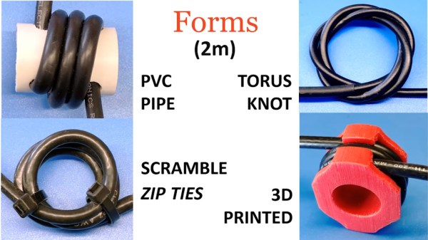
Most ham radio operators will build an antenna of some sort when they first start listening or transmitting, whether it’s a simple dipole, a beam antenna like a Yagi, or even just a random wire vertical antenna. All of these will need to be connected feedline of some sort, and in the likely event you reach for some 50-ohm coax cable you’ll also need a balun to reduce noise or unwanted radiation. Don’t be afraid of extra expenses when getting into this hobby, though, as [W6NBC] demonstrates how to construct an “ugly balun” out of the coax wire itself (PDF).

The main purpose of a balun, a contraction of “balanced-unbalanced” is to convert an unbalanced transmission line to a balanced one. However, as [W6NBC] explains, this explanation obscures much of what baluns are actually doing. In reality, they take a three-wire system (the coax) and convert it to a two-wire system (the antenna), which keeps all of the electrical noise and current on the shield wire of the coax from interfering with the desirable RF on the interior of the coax.

This might seem somewhat confusing on the surface, as coax wires only have a center conductor and a shield wire, but thanks to the skin effect which drives currents to the outside of the conductor, the shield wire effectively becomes two conductors when taking into account its inner and outer surfaces. At these high frequencies the balun is acting as a choke which keeps these two high-frequency conductors separate from one another, and keeps all the noise on the outside of the shield wire and out of the transmitter or receiver.

Granted, the world of high-frequency radio circuits can get quite complex and counter-intuitive and, as we’ve shown before, can behave quite unexpectedly when compared to DC or even mains-frequency AC. But a proper understanding of baluns and other types of transformers and the ways they interact with RF can be a powerful tool to have. We’eve even seen other hams use specialty transformers like these to make antennas out of random lengths and shapes of wire.

Continue reading “Don’t Let The Baluns Float Over Your Head”

Your Multimeter Might Be Lying To You

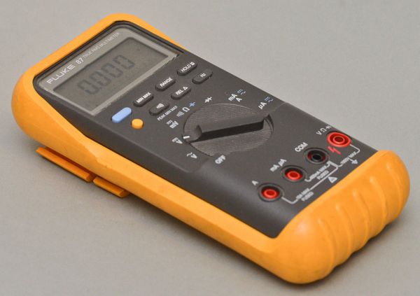
Multimeters are indispensable tools when working on electronics. It’s almost impossible to build any but the most basic of circuits without one to test and troubleshoot potential issues, and they make possible a large array of measurement capabilities that are not easily performed otherwise. But when things start getting a little more complex it’s important to know their limitations, specifically around what they will tell you about circuits designed for high frequency. [watersstanton] explains in this video while troubleshooting an antenna circuit for ham radio.

The issue that often confuses people new to radio or other high-frequency projects revolves around the continuity testing function found on most multimeters. While useful for testing wiring and making sure connections are solid, they typically only test using DC. When applying AC to the same circuits, inductors start to offer higher impedance and capacitors lower impedance, up to the point that they become open and short circuits respectively. The same happens to transformers, but can also most antennas which often look like short circuits to ground at DC but can offer just enough impedance at their designed frequency to efficiently resonate and send out radio waves.

This can give some confusing readings, such as when testing to make sure that a RF connector isn’t shorted out after soldering it to a coaxial cable for example. If an antenna is connected to the other side, it’s possible a meter will show a short at DC which might indicate a flaw in the soldering of the connector if the user isn’t mindful of this high-frequency impedance. We actually featured a unique antenna design recently that’s built entirely on a PCB that would show this DC short but behaves surprisingly well when sending out WiFi signals.

Continue reading “Your Multimeter Might Be Lying To You”

Antenna Hidden In Holiday Lights Skirts HOA Rules

For all their supposed benefits, homeowner’s associations (HOAs) have a reputation of quickly turning otherwise quaint neighborhoods into a sort of Stanford prison experiment, as those who get even the slightest amount of power often abuse it. Arbitrary rules and enforcement abound about house color, landscaping, parking, and if you’ve ever operated a radio, antennas. While the FCC (at least as far as the US is concerned) does say that HOAs aren’t permitted to restrict the use of antennas, if you don’t want to get on anyone’s bad side you’ll want to put up an antenna like this one which is disguised as a set of HOA-friendly holiday lights.

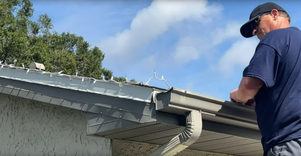
For this build, a long wire is hidden along with a strand of otherwise plain-looking lights. While this might seem straightforward at first, there are a few things that need to be changed on the lighting string in order to make both the antenna and the disguise work. First, the leads on each bulb were removed to to prevent any coupling from the antenna into the lighting string. Clipping the leads turns what is essentially a long wire that might resonate with the antenna’s frequency into many short sections of wire which won’t have this problem. This also solves the problem of accidentally illuminating any bulbs when transmitting, as the RF energy from the antenna could otherwise transfer into the lighting string and draw attention from the aforementioned HOA.

Tests of this antenna seemed to show surprising promise while it was on the ground, but when the string and antenna was attached to the roof fascia the performance dropped slightly, presumably because of either the metal drip edge or the gutters. Still, the antenna’s creator [Bob] aka [HOA Ham] had excellent success with this, making clear contacts with other ham radio operators hundreds of miles away. We’ve shared another of [Bob]’s HOA-friendly builds below as well which hides the HF antenna in the roof’s ridge vent, and if you’re looking for other interesting antenna builds take a look at this one which uses a unique transformer to get wide-band performance out of an otherwise short HF antenna.

Continue reading “Antenna Hidden In Holiday Lights Skirts HOA Rules”

High-Speed PCB Design Hack Chat With Bil Herd

Join us on Wednesday, September 25 at noon Pacific for the High-Speed PCB Design Hack Chat with Bil Herd!

Printed circuits have become so commoditized that we seldom think much about design details. EDA software makes it easy to forget about the subtleties and nuances that make themselves painfully obvious once your design comes back from the fab and doesn’t work quite the way you thought it would.

PCB design only gets more difficult the faster your circuit needs to go, and that’s where a depth of practical design experience can come in handy. Bil Herd, the legendary design engineer who worked on the Commodore C128 and Plus4/264 computers and many designs since then, knows a thing or two in this space, and he’s going to stop by the Hack Chat to talk about it. This is your chance to pick the brain of someone with a wealth of real-world experience in high-speed PCB design. Come along to find out what kind of design mistakes are waiting to make your day miserable, and which ones can be safely ignored. Spoiler alert: square corners probably don’t matter.

join-hack-chatOur Hack Chats are live community events in the Hackaday.io Hack Chat group messaging. This week we’ll be sitting down on Wednesday, September 25 at 12:00 PM Pacific time. If time zones have got you down, we have a handy time zone converter.

Click that speech bubble to the right, and you’ll be taken directly to the Hack Chat group on Hackaday.io. You don’t have to wait until Wednesday; join whenever you want and you can see what the community is talking about. Continue reading “High-Speed PCB Design Hack Chat With Bil Herd”

Help For High-Frequency Hobbyists

Dead-bug circuit building is not a pretty affair, but hey, function over form. We usually make them because we don’t have a copper circuit board available or the duty of making one at home is not worth the efforts and chemical stains.

[Robert Melville and Alaina G. Levine] bring to light a compromise for high-frequency prototypes which uses the typical FR4 blank circuit board, but no etching chemicals. The problem with high-frequency radio is that building a circuit on a breadboard will not work because there is too much added inductance and capacitance from the wiring that will wreak havoc on the whole circuit. The solution is not new, build your radio module on a circuit board by constructing “lands” over a conductive ground plane, where components can be isolated on the same unetched board.

All right, sometimes dead-bug circuits capture an aesthetic all their own, especially when they look like this and they do allow for a darned small package for one-off designs.

Model Of A Transmission Line

Transmission lines are the kind of thing that seems to confuse beginners. After all, the fact that short-circuits can have infinite impedance and open-circuits can behave like a short is not intuitive at all!. That’s why we like [Tinselkoala]’s latest video that shows a nice model of a transmission line. It helps to understand the line as inductors and capacitors in series-parallel connection.

Any pair of wires used to transmit electrical power have tiny amounts of inductance and capacitance. This is not a problem with DC or low-frequency AC, but when the frequency is sufficiently high, weird things start to happen. The energy tends to escape as radio waves, and current reflects from discontinuities such as connectors and cable joints.  For this reason, transmission lines for high frequency signals use specialized construction to minimize those effects and reduce power losses.

[Tinselkoala] has built a model of a transmission line using coils and capacitors to simulate the inductance and capacitance of the line, with LED’s placed between the coils. He feeds the system with the signal generator with frequencies from 10 kHz to 1 MHz. In his words, they act as simple “visual voltmeters” to show the peaks and nodes of the standing waves of voltage in the line.

It is relatively simple to build your own version if you want to experiment with this fascinating subject. You will only need some magnet wire, capacitors, resistors and LED’s. If the subject sounds interesting to you,  here you can find an excellent introduction to transmission lines.

Continue reading “Model Of A Transmission Line”