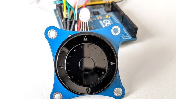
Creating capacitive touch-sensitive buttons is easy these days; many microcontrollers have cap-sense hardware built-in. This will work for simple on/off control, but what if you want a linear, position-sensitive input, like you’d find on a computer touchpad or your smartphone screen? Not so easy — at least until now. Trill is a family of capacitive touch sensors you can add to your projects as a linear slider, a square touchpad, or by creating your own touch surface.
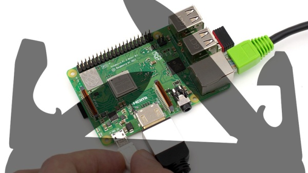
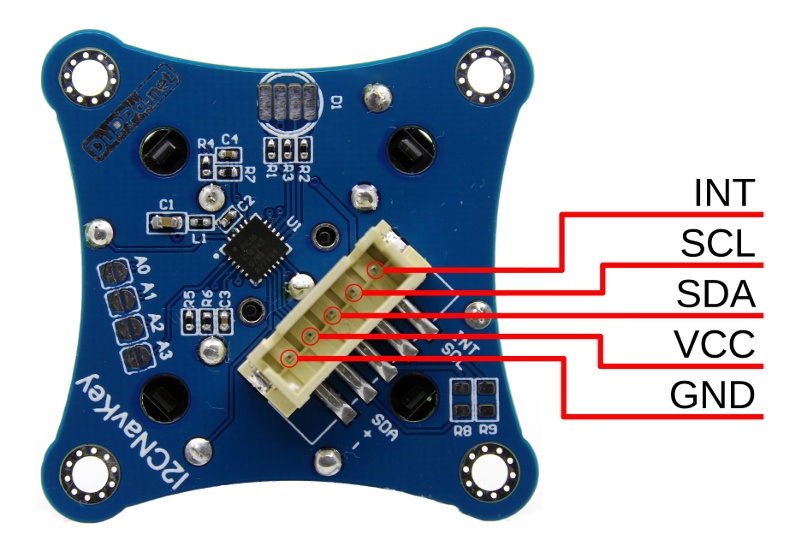
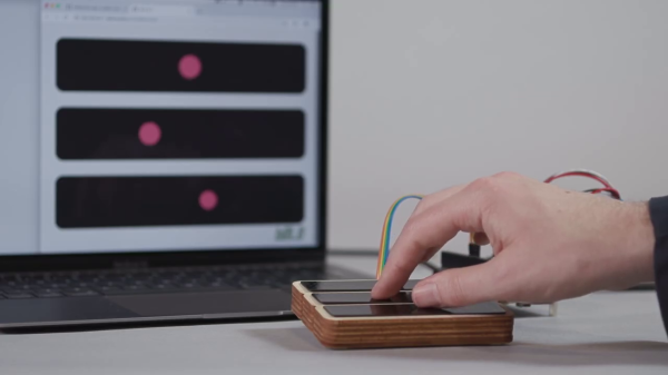
Trill was created by the same team that designed Bela, an embedded platform for low-latency interactive applications, especially with audio. The new trio of Trill sensors rely on capacitive sensing to track finger movement, and communicate over I2C with your microcontroller or development board of choice. The Trill I2C library targets Arduino and Bela, but should be easy to port to any I2C host.
The hardware and software are both open-source — or will be as the Kickstarter that launched this morning has already met its goal. The firmware for the Cypress CY8C20636A (PDF) controller that powers these sensors will be released CC-BY-NC-SA. But, starting with the controller itself sounds like a lot of work that Trill has already done for you, so let’s have a look at what we know so far, along with a healthy dose of speculation.
Continue reading “Trill: Easy Positional Touch Sensors For Your Projects”