Wii Nunchuk Gets A Built-in Raspberry Pi Zero

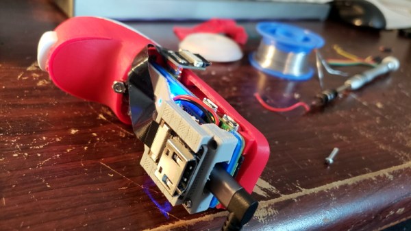
The Wii controller will likely go down in history as the hacker’s favorite repurposed input device, and there’s no question that the Raspberry Pi is the community’s top pick in terms of Linux single board computers. So it should come as little surprise that somebody has finally given us the cross-over episode that the hacking community deserves: the PiChuk, a Pi Zero inside of Nintendo’s motion-sensing “nunchuk”.

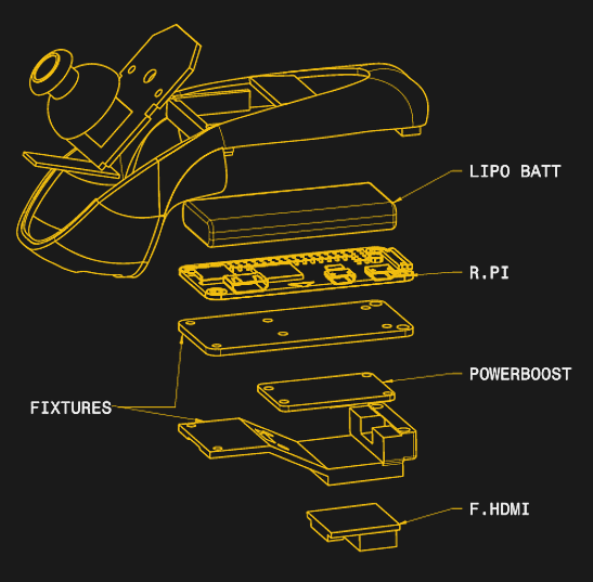
Veterans of Wii Sports might be wondering how the hero of our story, a hacker by the name of [keycaps], managed to pull off such a feat. The Pi Zero is small, but it’s not that small. The trick is that the case of the nunchuk has been extended by way of a new 3D printed bottom half.

There’s more than just a Pi Zero along for the ride, as well. [keycaps] has manged to sneak in a 750 mAh LiPo and an Adafruit Powerboost, making the device a completely self-contained system. Interestingly, the original nunchuk PCB remains more or less untouched, with just a couple of wires connected to the Pi’s GPIO ports so it can read the button and stick states over I2C.

We know you’re wondering why [keycaps] went through the trouble of breaking out the HDMI port on the bottom. It turns out, the PiChuk is being used to drive a Vufine wearable display; think Google Glass, but without the built-in computing power. The analog stick and motion sensing capabilities of the controller should make for a very natural input scheme, as far as wearable computers go.

So not only could the PiChuk make for an awesome wireless input device for your next project, it’s actually a pretty strong entry into the long line of wearable computing devices based on the Pi. Usually these have included a DIY version of the distinctive Google Glass display, but offloading that onto a commercially available version is certainly a lot easier.

A Raspberry Pi Is A Hardware Hacker’s Swiss Army Knife

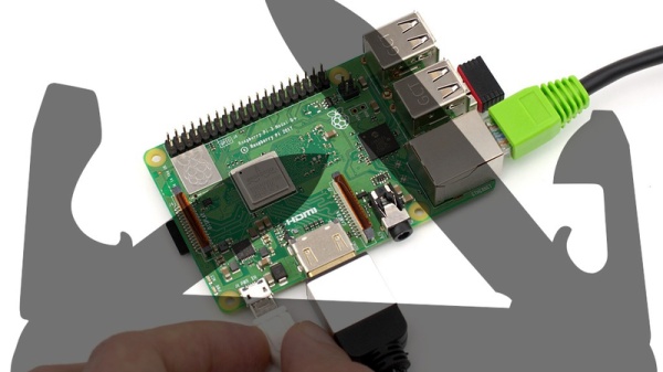
By now most of us have used a Raspberry Pi at some level or another. As a headless server it’s a great tool because of its price point, and as an interface to the outside world the GPIO pins are incredibly easy to access with a simple Python script. For anyone looking for guidance on using this device at a higher level, though, [Arun] recently created a how-to for using some of the Pi’s available communications protocols.

Intended to be a do-everything “poor man’s hardware hacking tool” as [Arun] claims, his instruction manual details all the ways that a Raspberry Pi can communicate with other devices using SPI and I2C, two of the most common methods of interacting with other hardware beyond simple relays. If you need to go deeper, the Pi can also be used as a full JTAG interface or SWD programmer for ARM chips. Naturally, UART serial is baked in. What more do you need?

As either a tool to keep in your toolbox for all the times you need to communicate with various pieces of hardware, or as a primer for understanding more intricate ways of using a Raspberry Pi to communicate with things like sensors or other computers, this is a great write-up. We also have more information about SPI if you’re curious as to how the protocol works.

Thanks to [Adrian] for the tip!

A Bolt-On I2C Navigation Key For Your Next Project

We often talk about the advantages of modular hardware here at Hackaday; the ability to just order a few parts online, hook them up with some jumper wires, and move onto the software side of things is a monumental time saver when it comes to prototyping. So anytime we see a new module that’s going to save us time and aggravation down the road, we get a bit excited.

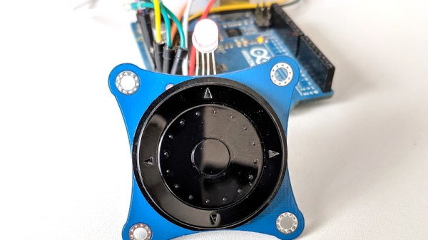
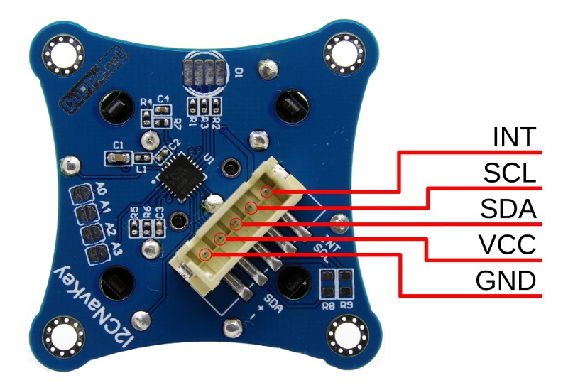
Today we present the very slick I2CNavKey developed by [Saimon], a turn-key interface solution for your builds that can’t quite get away with a couple toggle switches. It not only gives you a four-way directional pad with center button, but a rotary “wheel” like on the old iPods. All of which you can access easily and with a minimum of wiring thanks to the wonders of I2C.

But even that might be selling the module short. This isn’t just a couple of buttons on a breakout board, the I2CNavKey is powered by its own PIC16F18345 microcontroller and features three configurable GPIOs with PWM support (perfect for an RGB LED) plus 256 bytes of onboard EEPROM storage.

[Saimon] has released the entire project as open source hardware for your hacking pleasure, but you can also get them as ready-to-use modules on Tindie for $18 USD [Editor’s Note: Because of a typo we originally we left the 1 out of the price]. Whether you’re a paying customer or not, you get access to the project’s absolutely phenomenal documentation, including a nearly 30 page manual that contains everything you’d ever want to know about the I2CNavKey and how to integrate it into your project. If all hardware was documented with this level of dedication, the world would be a much nicer place for folks like us.

If you recognize the name, or perhaps the affinity for neat I2C-connected input devices, it’s probably because you’ve seen his very similar I2C rotary encoder on these pages previously, which was a finalist in our Open Hardware Design Challenge during the 2018 Hackaday Prize.

Teardown: AppLights Personalized Projection

Listen, it hurts to hear, but somebody needs to say it. It’s over, OK? You’ve got to admit it and move on. Sure, you could get away with it for a week or two in January, but now it’s just getting weird. No matter how hard you fight it, the facts are the facts: the holidays are over. It’s time to pack up all those lights and decorations before the neighbors really start talking.

Fun Fact: It can’t actually do this

But don’t worry, because there’s an upside. Retailers are now gearing up for their next big selling season, which means right now clearance racks the world over are likely to be playing home to holiday lights and decor. That wouldn’t have been very interesting to the average hacker or maker a few years ago, after all, there’s only so much you can do with a string of twinkle lights. But today, holiday decorations are dripping with the sort of high-tech features you’d expect from gadgets that are actively aiming to be obsolete within the next ten months or so.

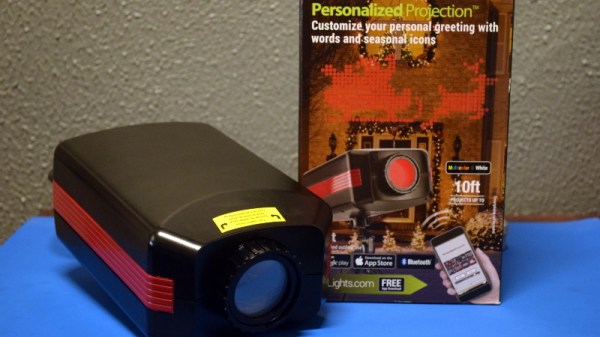
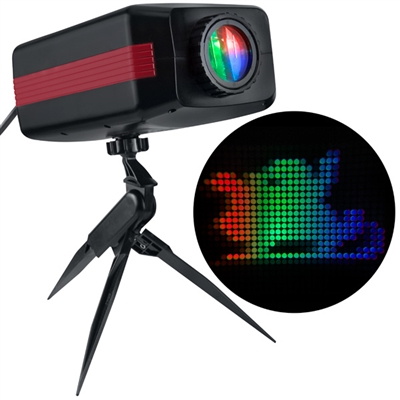
Case in point, the “AppLights Personalized Projection” which I found sulking around the clearance section of the Home Depot a couple weeks back. This device advertises the ability to project multi-color custom messages and animations on your wall, and is configured over Bluetooth with a companion application on your Android or iOS device. At a minimum we can assume the device must contain a fairly powerful RGB LED, an LCD to shine the light through, and some sort of Bluetooth-compatible microcontroller. For $20 USD, I thought it was worth taking a shot on.

Around this time last year, the regular Hackaday reader may recall I did a teardown for a Christmas laser projector. Inside we found red, green, and blue lasers of considerable power, as well as all the optics and support hardware to get them running. It was a veritable laser playground for $14. Let’s see if the AppLights projector turns out to be a similar electronic cornucopia, and whether or not we’ve got a new Hackaday Holiday tradition on our hands.

Continue reading “Teardown: AppLights Personalized Projection”

Multiple OLEDs? Save Pins By Sharing The I2C Clock

Inexpensive OLED displays with I2C interfaces abound, but there is a catch: they tend to be stuck on I2C address 0x3C. Some have a jumper or solder pads to select an alternate (usually 0x3D), but they lack any other method. Since an I2C bus expects every device to have a unique address, this limits the number of displays per bus to one (or two, at best.) That is all still true, but what [Larry Bank] discovered is a way to get multiple OLED displays working with considerably fewer microcontroller pins than usually needed.

While bit-banging I2C to host one display per bus on the same microcontroller, an idea occurred to him. The I2C start signal requires both clock (SCL) and data (SDA) to be brought low together, but what would happen if the displays shared a single clock line? To be clear, each OLED would — logically speaking — still be on its own I2C bus with its own data line, but they would share a clock signal. Would a shared clock cause attached devices to activate unintentionally?

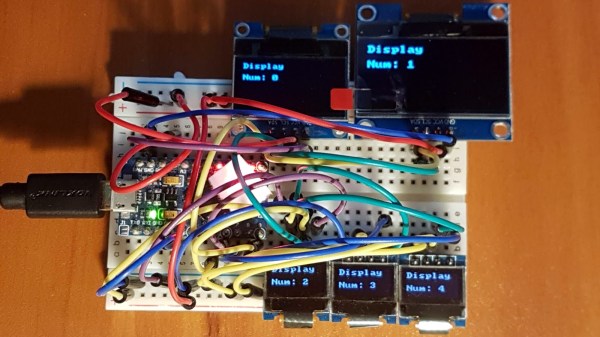
A quick test consisting of four OLED displays (all with address 0x3C) showed that it was indeed possible to address each display with no interference if they shared a clock. Those four individually controlled displays needed only five I/O lines (four SDA, one shared SCL) instead of eight. The Multi_OLED library is available on GitHub, and in case it is useful for devices other than OLED displays, bit-banged I2C with support for shared clock lines is available separately.

There’s more to do with OLEDs than get clever with signals: check out these slick number-change animations, and that even looks to be a project that could benefit from a few saved GPIO pins, since it uses one small display per digit.

Two Joysticks Talk To FPGA Arcade Game Over A VGA Cable

We really love when hacks of previous hacks show up in the tip line. It shows how the hardware hacking community can be a feedback loop, where one hack begets the next, and so on until great things are everywhere. This hacked joystick port for an FPGA Pac Man game is a perfect example of that creative churn.

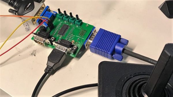
The story starts with Pano Man, a version of the venerable arcade game ported to a Pano Logic FPGA thin client by [Skip]. We covered that story when it first came out, and it caught the attention of [Tom Verbeure], particularly the bit in the GitHub readme file which suggested there might be a better way to handle the joystick connections. So [Tom] took up the challenge of using the Extended Display Identification Data (EDID) circuit in the VGA connector to support an Atari 2600 joystick. The EDID system is an I²C bus, so the job needed the right port expander. [Tom] chose the MCP23017, a 16-bit device that would have enough GPIO for dual joysticks and a few extra buttons. Having never designed a PCB before, [Tom] fell down that rabbit hole for a bit, but quickly came up with a working design, and then a better one, and then the final version. The video below shows it in action with Pano Man.

We think the creative loop between [Skip] and [Tom] was great here, and we can’t wait to see who escalates next. And it’s pretty amazing how much IO can be stuffed over two wires if you have the right tools. Check out this VGA sniffing effort to learn more about EDID and I²C.

Continue reading “Two Joysticks Talk To FPGA Arcade Game Over A VGA Cable”

Modernizing A Soviet-era LED Matrix

Used in everything from calculators to military hardware, the 3LS363A is an interesting piece of vintage hardware. With a resolution of 5 x 7 (plus a decimal point), the Soviet-made displays contain no electronics and are simply an array of 36 green LEDs. It’s not hard to drive one of them in a pinch, but [Dmitry Grinberg] thought this classic device deserved a bit better than the minimum.

He’s developed a small board that sits behind the 3LS363A and allows you to control it over I2C for a much more modern experience when working with these vintage displays. Powered by the ATtiny406, his adapter board makes it easy to chain the modules together and even handles niceties like flipping the displayed image to account for different mounting positions. While most of us probably won’t have the chance to play around with these relatively rare displays, there’s still plenty of useful information here if you’re thinking of creating your own I2C gadgets.

In his write-up, [Dmitry] explains his rationale behind the design and some of the quirks of working with the display. For example he explains how he gave each column of the display its own FET, but to save space on the board ended up running the single decimal point (technically its own column) directly off of a spare GPIO pin. Relying on the low duty cycle, he even left current limiting resistors off the design. The end result is a tiny board that keeps the same footprint of the 3LS363A itself.

[Dmitry] went all out with developing the firmware for his new “smart” 3LS363A displays, and has written up documentation for the different commands he has implemented. From re-configuring the I2C address to updating the firmware, he’s made sure no stone was left unturned for this project. We’re not ones to shy away from a quick and dirty code, but it’s always nice to see when somebody has really put some thought into the software side of a project.

We’ve seen our fair share of oddball Soviet displays here at Hackaday, utilizing everything from heavy duty incandescent bulbs to remarkably tiny “intelligent” LEDs. While it’s unlikely any of them will dethrone the nixie as king of the retro display devices, it’s always interesting to see unusual hardware being used in the wild.