Modernizing A Soviet-era LED Matrix

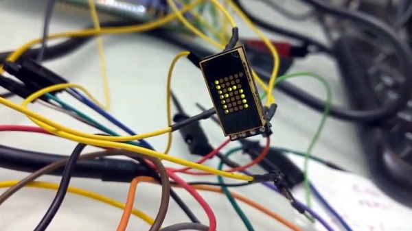
Used in everything from calculators to military hardware, the 3LS363A is an interesting piece of vintage hardware. With a resolution of 5 x 7 (plus a decimal point), the Soviet-made displays contain no electronics and are simply an array of 36 green LEDs. It’s not hard to drive one of them in a pinch, but [Dmitry Grinberg] thought this classic device deserved a bit better than the minimum.

He’s developed a small board that sits behind the 3LS363A and allows you to control it over I2C for a much more modern experience when working with these vintage displays. Powered by the ATtiny406, his adapter board makes it easy to chain the modules together and even handles niceties like flipping the displayed image to account for different mounting positions. While most of us probably won’t have the chance to play around with these relatively rare displays, there’s still plenty of useful information here if you’re thinking of creating your own I2C gadgets.

In his write-up, [Dmitry] explains his rationale behind the design and some of the quirks of working with the display. For example he explains how he gave each column of the display its own FET, but to save space on the board ended up running the single decimal point (technically its own column) directly off of a spare GPIO pin. Relying on the low duty cycle, he even left current limiting resistors off the design. The end result is a tiny board that keeps the same footprint of the 3LS363A itself.

[Dmitry] went all out with developing the firmware for his new “smart” 3LS363A displays, and has written up documentation for the different commands he has implemented. From re-configuring the I2C address to updating the firmware, he’s made sure no stone was left unturned for this project. We’re not ones to shy away from a quick and dirty code, but it’s always nice to see when somebody has really put some thought into the software side of a project.

We’ve seen our fair share of oddball Soviet displays here at Hackaday, utilizing everything from heavy duty incandescent bulbs to remarkably tiny “intelligent” LEDs. While it’s unlikely any of them will dethrone the nixie as king of the retro display devices, it’s always interesting to see unusual hardware being used in the wild.
Arduino And Pi Share Boardspace

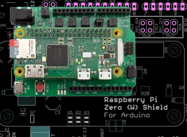
A Raspberry Pi Zero (W) and Arduino are very different animals, the prior has processing power and connectivity while the latter has some analog to digital converters (ADCs) and nearly real-time reactions. You can connect them to one another with a USB cable and for many projects that will happily wed the two. Beyond that, we can interface this odd couple entirely through serial, SPI, I2C, and logic-level signaling. How? Through a device by [cburgess] that is being called an Arduino shield that supports a Pi0 (W). Maybe it is a cape which interfaces with Arduino. The distinction may be moot since each board has a familiar footprint and both of them are found here.

Depending on how they are set up and programmed, one can take control over the other, or they could happily do their own thing and just exchange a little information. This board is like a marriage counselor between a Raspberry Pi and an Arduino. It provides the level-shifting so they don’t blow each other up and libraries so they can speak nicely to one another. If you want to dig a bit deeper into this one, design files and code examples are on available.

Perhaps we’ll report on this board at the heart of a pinball machine retrofit, a vintage vending machine restoration, or maybe a working prop replica from the retro bar in Back to the Future II.

Every Computer Deserves A Rotary Encoder

In the era of touch screens and capacitive buttons, we’d be lying if we said we didn’t have the occasional pang of nostalgia for the good old days when interfacing with devices had a bit more heft to it. The physical clunk and snap of switches never seems to get old, and while you can always pick up a mechanical keyboard for your computer if you want to hear that beautiful staccato sound while firing off your angry Tweets, there’s a definite dearth of mechanical interface devices otherwise.

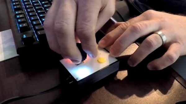
[Jeremy Cook] decided to take matters into his own hands (literally and figuratively) by designing his own multipurpose USB rotary input device. It’s not a replacement for the mouse or keyboard, but a third pillar of the desktop which offers a unique way of controlling software. It’s naturally suited to controlling things like volume or any other variable which would benefit from some fine tuning, but as demonstrated in the video after the break even has some gaming applications. No doubt the good readers of Hackaday could think of even more potential applications for a gadget like this.

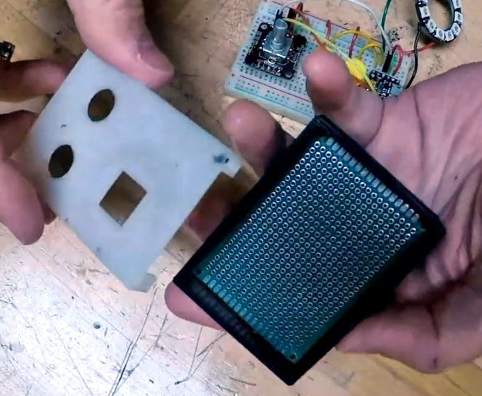
The device is built around the diminutive Arduino-compatible PICO board by MellBell, which features a ATmega32u4 and native USB. This allowed him to very rapidly spin up a USB Human Interface Device (HID) with minimal headaches, all he had to do was hang his buttons and rotary encoder on the PICO’s digital pins. To that end, he [Jeremy] used the fantastic I2C rotary encoder designed by [fattore.saimon], which readers may remember as a finalist in the Open Hardware Design Challenge phase of the 2018 Hackaday Prize. He also added a NeoPixel ring around the encoder to use for some visual feedback and because, well, it just looks cool.

Since all of the core components are digital, there’s not a whole lot required in the way of wiring or passive components. This let [Jeremy] put the whole thing together on a piece of perfboard, freeing him up to spend time designing the 3D printed enclosure complete with translucent lid so he can see the NeoPixel blinkenlights. He got the tolerances tight enough that the whole device can be neatly press-fit together, and even thought to add holes in the bottom of the case so he could push the perfboard back out if he needed to down the line.

[Jeremy] spends a good chunk of the video going over the software setup and development of the firmware, and details some of the nuances he had to wrap his head around when working with the I2C encoder. He also explains the math involved in getting his encoder to emulate a mouse cursor moving in a circle, which he thinks could be useful when emulating games that originally used an encoder such as Tempest or Pong.

We’ve seen similar USB “knobs” in the past for controlling volume, but the additional inputs that [Jeremy] built into his version definitely makes it a bit more practical. Of course we’re suckers for interesting USB input devices to begin with.

Continue reading “Every Computer Deserves A Rotary Encoder” →

Open Hardware Board For Robust USB Power Monitoring

We’ve all seen the little USB power meters that have become popular since nearly every portable device has adopted some variation of USB for charging. Placed between the power source and the device under test, they allow you to see voltage and current in real time. Perfect for determining how long you’ll be able to run a USB powered device on batteries, or finding out if a USB power supply has enough current to do the business.

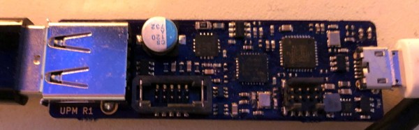
[Jonas Persson] liked the idea of these cheap little gadgets, but wanted something a bit more scientific. His design, which he refers to as UPM, is essentially a “smart” version of those ubiquitous USB gadgets. Instead of just showing the data on a little LCD screen, it can now be viewed on the computer and analyzed. His little gadget even allows you to cut power to the device under test, potentially allowing for automated testing of things such as inrush current.

Essentially the UPM works in much the same way as the simple USB meters: one side of the device goes towards the upstream power source, and the device under test plugs into the other side. Between the two devices is a 16 bit ADC and differential amplifier which measures the voltage and current. There’s a header on the board which connects to the ADC if you wanted to connect the UPM to an external microcontroller or other data logging device.

But most likely you would be using the internal microcontroller to analyze the output of the ADC over I2C, which [Jonas] very cleverly connected to the upstream port with an integrated USB hub. One side of the hub goes off to the device being tested, and the other to the microcontroller. So the host device will see both the UPM’s integrated microcontroller and the target device at the same time. From there, you can use the ncurses user interface to monitor and control the device in real-time.

While the hardware looks more or less finished, [Jonas] has some more plans for the software side of UPM, including support for remote control and monitoring over TCP/IP as well as robust logging capabilities. This is definitely a very interesting project, and we’re excited to see it develop further.

In the past we’ve seen homebrew USB power meter builds, and even commercial offerings which boasted computer-based logging and analysis, so it was only a matter of time before somebody combined them into one.

From SPIDriver To I2CDriver

Communicating with microcontrollers and other embedded systems requires a communications standard. SPI is a great one, and is commonly used, but it’s not the only one available. There’s also I2C which has some advantages and disadvantages compared to SPI. The problem with both standards, however, is that modern computers don’t come with either built-in. To solve that problem and allow easier access to debugging in SPI, [James Bowman] built the SPIDriver a few months ago, and is now back by popular demand with a similar device for I2C, the I2CDriver.

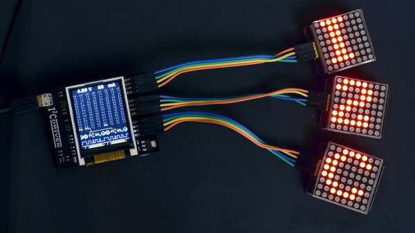
Much like the SPIDriver, the I2C driver is a debugging tool that can be used at your computer with a USB interface. Working with I2C is often a hassle, with many things going on all at once that need to sync up just right in order to work at all, and this device allows the user to set up I2C devices in a fraction of the time. To start, it has a screen built in that shows information about the current device, like the signal lines and a graphical decoding of the current traffic. It also shows an address space map, and has programmable pullup resistors built in, and can send data about the I2C traffic back to its host PC for analysis.

The I2CDriver is also completely open source, from the hardware to the software, meaning you could build one from scratch if you have the will and the parts, or make changes to the code on your own to suit your specific needs. If you’re stuck using SPI still, though, you can still find the original SPIDriver tool to help you with your debugging needs with that protocol as well.

Arduino Gets A Command Line Interface

When using an Arduino, at least once you’ve made it past blinking LEDs, you might start making use of the serial connection to send and receive information from the microcontroller. Communicating with the board while it’s interacting with its environment is a crucial way to get information in real-time. Usually, that’s as far as it goes, but [Pieter] wanted to take it a step farther than that with his command line interpreter (CLI) for the Arduino.

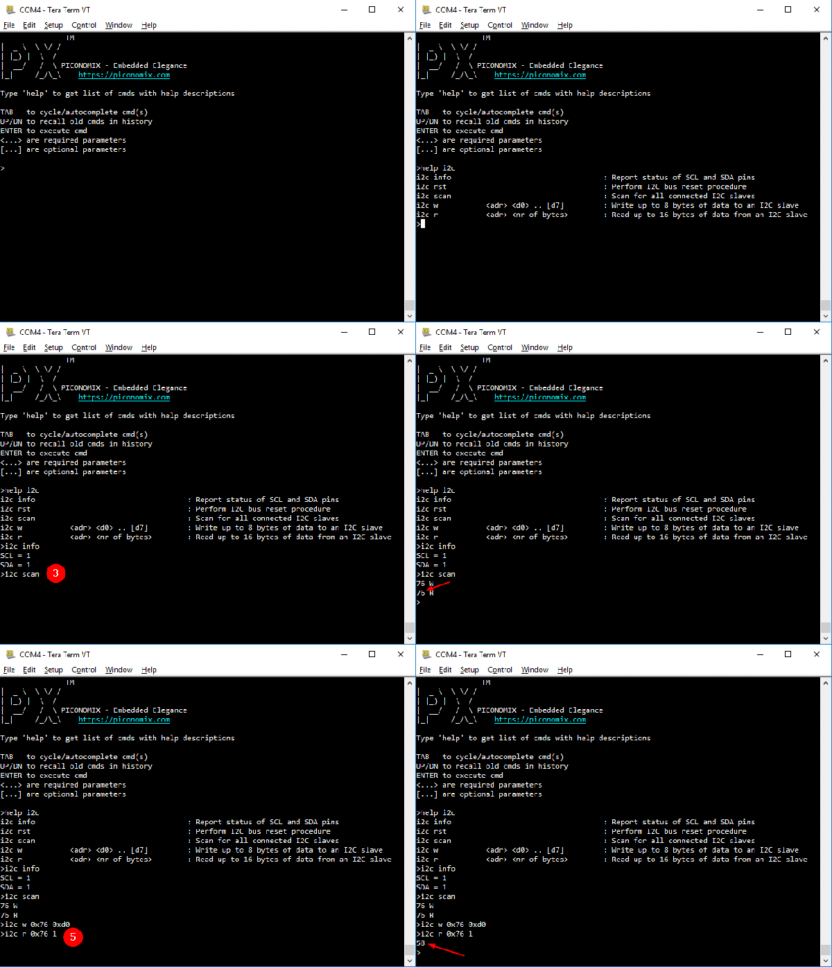
The CLI allows the user to run Unix-like commands directly on the Arduino. This means control of GPIO and the rest of the features of the microcontroller via command line. The CLI communicates between the microcontroller and the ANSI/VT100 terminal emulator of your choosing on your computer, enabling a wealth of new methods of interacting with an Arduino.

The CLI requires a hex file to be loaded onto the Arduino that you can find at a separate site, also maintained by [Pieter]. Once that’s running, you can get all of that sweet command line goodness out of your Arduino. [Pieter] also has some examples on his project page, as well as the complete how-to to get this all set up and running. There’s a lot going on in the command line world, in Linux as well as windows. So there’s plenty to explore there as well.

Rooting The Amazon Fire TV Cube With An Arduino

Amazon might not be happy about it, but at least part of the success of their Fire TV Stick was due to the large hacking and modification scene that cropped up around the Android-powered device. A quick search on YouTube for “Fire Stick Hack” will bring up a seemingly endless array of videos, some with millions of views, which will show viewers how to install unofficial software on the little media dongle. Now it looks like their latest media device, the Fire TV Cube, is starting to attract the same kind of attention.

The team at [Exploitee.rs] has recently taken the wraps off their research which shows the new Fire TV Cube can be rooted with nothing more than an Arduino and an HDMI cable you’re willing to cut apart. Of course, it’s a bit more complicated than just that, but between the video they’ve provided and their WiKi, it looks like all the information is out there for anyone who wants to crack open their own Cube. Just don’t be surprised if it puts you on the Amazon Naughty List.

The process starts by putting the device’s Amlogic S905Z into Device Firmware Upgrade (DFU) mode, which is done by sending the string “boot@USB” to the board over the HDMI port’s I2C interface. That’s where the HDMI cable comes in: you can cut into one and wire it right up to your Arduino and run the sketch [Exploitee.rs] has provided to send the appropriate command. Of course, if you want to get fancy, you could use an HDMI breakout board instead.

With the board in DFU mode in you gain read and write access to the device’s eMMC flash, but that doesn’t exactly get you in because there’s still secure boot to contend with. But as these things tend to go, the team was able to identify a second exploit which could be used in conjunction with DFU mode to trick the device into disabling signature verification. Now with the ability to run unsigned code on the Fire TV Cube, [Exploitee.rs] implemented fastboot to make it easier to flash their custom rooted firmware images to the hardware.

As with the Fire TV Stick before it, make sure you understand the risks involved when you switch off a device’s security features. They’re often there to protect the end user as much as the manufacturer.

Continue reading “Rooting The Amazon Fire TV Cube With An Arduino” →