[Chordata] is making a motion capture system for everyone to build and so far the results are impressive, enough to have been a finalist in the Hackaday Human Computer Interface Challenge. It started a few years ago as one person’s desire to capture a digital performance of a dancer on a stage and has grown into a community of contributors. The board files and software have just been released as alpha along with some instructions for making it work, though more detailed documentation is on the way.
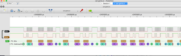
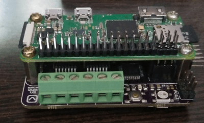
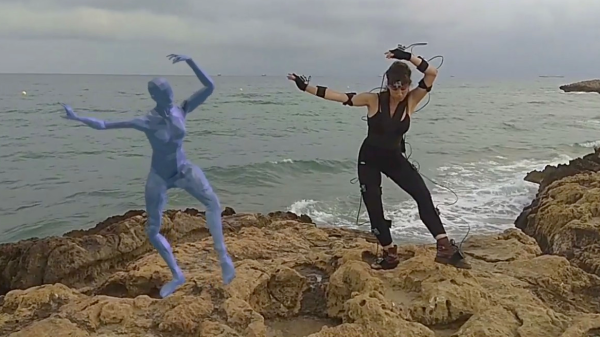
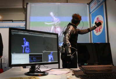 Fifteen sensor boards, called K-Ceptors, are attached to various points on the body, each containing an LSM9DS1 IMU (Inertial Measurement Unit). The K-Ceptors are wired together while still allowing plenty of freedom to move around. Communication is via I2C to a Raspberry Pi. The Pi then sends the collected data over WiFi to a desktop machine. As you move around, a 3D model of a human figure follows in realtime, displayed on the desktop’s screen using Blender, a popular, free 3D modeling software. Of course, you can do something else with the data if you want, perhaps make a robot move? Check out the overview and the performance by a clearly experienced dancer putting the system through its paces in the video below.
As a side note, the latest log entry on their Hackaday.io page points out that whenever changes are made to the K-Ceptor board, fifteen of them need to be made in order to try it out. To help with that, they show the testbed they made for troubleshooting boards as soon as they come out of the oven.