Dress Up Your 3D Prints With Toner-Transfer Labels

We’ve always found the various methods for adding text and graphics to 3D prints somewhat underwhelming. Embossed or debossed characters are fuzzy, at best, and multi-color printers always seem to bleed one color into the next. Still, the need for labels and logos is common enough that it’s worth exploring other methods, such as this easy toner transfer trick.

Home PCB makers will probably find the method [Squalius] describes in the video below very familiar, and with good reason. We’ve seen toner transfer used to mask PCBs before etching, and the basic process here is very similar. It starts with printing the desired graphics on regular paper using a laser printer; don’t forget to mirror the print. The printed surface is scuffed up a bit, carefully cleaned, and coated with a thick layer of liquid acrylic medium, of the kind used in paint pouring. The mirrored print is carefully laid on the acrylic, toner-side down, and more medium is brushed on the back of the paper. After the print dries, the paper is removed with a little water and some gentle friction, leaving the toner behind. A coat of polyurethane protects the artwork reasonably well.

[Squalius] has tested the method with PLA and PETG and reports good results. The text is clear and sharp, and even fine text and dithered graphics look pretty good. Durability could be better, and [Squalius] is looking for alternative products that might work better for high-wear applications. It looks like it works best on lightly textured surfaces, too, as opposed to surfaces with layer lines. We’d love to see if color laser prints work, too; [Squalius] says that’s in the works, and we’ve seen examples before that are reason for optimism.

Continue reading “Dress Up Your 3D Prints With Toner-Transfer Labels”

3D Printing A Bottle Labeling Assembly Line

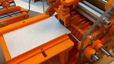
We’re not completely sure why [Fraens] needs to label so many glass bottles at home. Perhaps he’s brewing his own beer, or making jams. Whatever the reason is, it was justification enough to build an absolutely incredible labeling machine that you could mistake for a piece of industrial gear…if it wasn’t for the fact that majority of the device is constructed out of orange 3D printed plastic.

As we’ve come to expect, [Fraens] has documented the build with a detailed write-up on his site — but in this case, you’ve really got to watch the video below to truly appreciate how intricate the operation of this machine is. Watching it reminded us of an episode of How It’s Made, with the added bonus that you not only get to see how the machine functions, but how it was built in the first place.

Nearly every part of the machine, outside the fasteners, smooth rods, a couple of acrylic panels, and a few sections of aluminum extrusion, were 3D printed. You might think this would result in a wobbly machine with sloppy tolerances, but [Fraens] is truly a master of knowing when and where you can get away with using printed parts. So for example, while the glue rollers could be done in printed plastic, they still needed metal rods run through the middle for strength and proper bearings to rotate on.

Looking at the totality of this build, it’s hard to imagine how it could have been accomplished via traditional methods. Sure you could have sourced the rollers and gears from a supplier to save some plastic (at an added expense, no doubt), but there’s so many unique components that simply needed to be fabricated. For example, all the guides that keep the label heading in the right direction through the mechanism, or the interchangeable collars which let you select the pattern of glue which is to be applied. Maybe if you had a whole machine shop at your disposal, but that’s a lot more expensive and complex a proposition than the pair of desktop 3D printers [Fraens] used to crank out this masterpiece.

If the name (and penchant for orange plastic) seems familiar, it’s because we’ve featured several builds from [Fraens] in the past. This one may be the most technically impressive so far, but that doesn’t diminish the brilliance of his vibratory rock tumbler or cigarette stuffing machine.

Continue reading “3D Printing A Bottle Labeling Assembly Line”

Polish Up Your Product With Graphic Overlays

[Kevin Hunckler] recently did some in-house manufacturing for a product and shared his experiences in adding high-quality custom graphic overlays or acrylic panels to give the finished units a professional look. The results look great and were easy to apply, making his product more attractive without needing much assembly work.

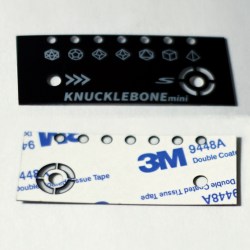
A graphic overlay with transparent areas, a cutout, and adhesive backing to fit an off-the-shelf Hammond enclosure.

Sadly, when doing initial research he was disappointed to find very little information on the whole process. While in the end it isn’t terribly complex, it still involved a lot of trial and error before he zeroed in on what the suppliers in the industry expect. Fortunately, everything can be done with tools most hackers probably already have access to.

The process seems to us somewhat reminiscent of having PCBs manufactured. One defines the product housing, outlines the overlay, creates the artwork, defines an adhesive layer, and makes a design document explaining each layer and important feature. [Kevin] provides examples of his work, one of which fits an off-the-shelf Hammond enclosure.

Professionally-made acrylic panels or graphic overlays is something worth keeping in mind for hobbyists and those who might engage in desktop manufacturing, as long as the costs are acceptable. Rather like PCBs, costs go down as quantities go up. [Kevin]’s 50 mm x 50 mm overlay cost about 1 USD each in quantity 200, but only 0.50 USD each when buying 500.

These may be great for low or middling quantities, but that doesn’t mean one is out of options for prototypes or micro quantities. We have seen fantastic results adding full-color images to 3D prints, and even using a 3D printer to draw labels directly onto prints.

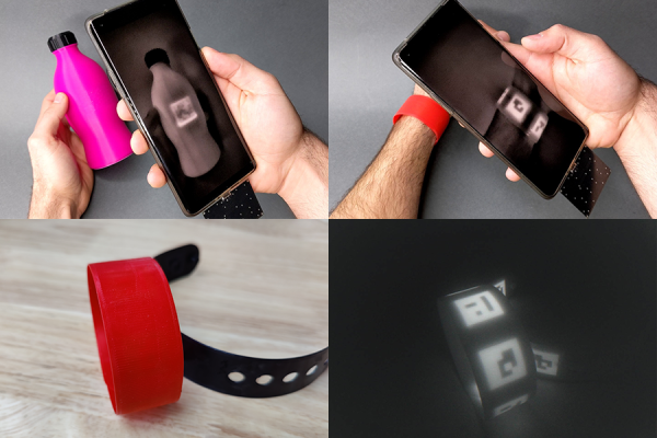
Four images in as many panes. Top left is a fuchsia bottle with a QR code that only shows up on the smartphone screen held above it. Top right image is A person holding a smartphone over a red wristband. The phone displays a QR code on its screen that it sees but is invisible in the visible wavelengths. Bottom left is a closeup of the red wristband in visible light and the bottom right image is the wristband in IR showing the three QR codes embedded in the object.

Fluorescent Filament Makes Object Identification Easier

QR codes are a handy way to embed information, but they aren’t exactly pretty. New work from MIT’s Computer Science and Artificial Intelligence Laboratory (CSAIL) have a new way to produce high contrast QR codes that are invisible. [PDF]

If this sounds familiar, you may remember CSAILs previous project embedding QR codes into 3D prints via IR-transparent filament. This followup to that research increases the detection of the objects by using an IR-fluorescent filament. Another benefit of this new approach is that while the InfraredTags could be any color you wanted as long as it was black, BrightMarkers can be embedded in objects of any color since the important IR component is embedded in traditional filament instead of the other way around.

One of the more interesting applications is privacy-preserving object detection since the computer vision system only “sees” the fluorescent objects. The example given is marking a box of valuables in a home to be detected by interior cameras without recording the movements of the home’s occupants, but the possibilities certainly don’t end there, especially given the other stated application of tactile interfaces for VR or AR systems.

We’re interested to see if the researchers can figure out how to tune the filament to fluoresce in more colors to increase the information density of the codes. Now, go forth and 3D print a snake with snake in a QR code inside!

Continue reading “Fluorescent Filament Makes Object Identification Easier”

DIY Automated Printer Kerchunks Out Classic Embossed Labels

For our money, the best label for pretty much any purpose is one of those embossed Dymo-style stick-on labels, the kind with the raised white letters. There’s just something about them — the raised letters just beg to be touched, their legibility is outstanding, they lend an unmatched retro feel to a project, and the experience of creating one with one of those manual kerchunkers is oddly satisfying.

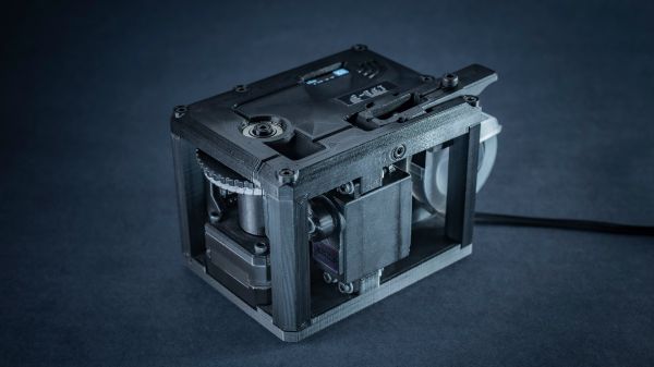
But alas, those manual label makers aren’t what they used to be, as [Andrei Speridião] discovered when his fell apart in his hands. Rather than complain, he automated his label maker and turned it into a computer peripheral.  Dubbed “E-TKT”, the DIY label printer takes the daisy-wheel embossing die from his defunct labeler and puts it under computer control. Rather than the ratchet mechanism of the original, a stepper motor advances the tape, another stepper rotates the wheel to the correct position, and a servo does the kerchunking duty. The process repeats until the label is complete and neatly cut off, ready to apply. An ESP32 runs the mechanism and serves up a web application to compose labels and control the printer. There’s also an OLED display and, of course, an embossed label. Video demo below.

We don’t care what [Bart Simpson] thinks, embossed labels are cool, and this makes them even cooler. And as [Andrei] points out, this is also a neat way around the nasty DRM trick that some companies are foisting on the label-making public. That alone is reason to cheer this project on — but we won’t complain about the beautiful photography and excellent documentation, either.

Continue reading “DIY Automated Printer Kerchunks Out Classic Embossed Labels”

Invisible 3D Printed Codes Make Objects Interactive

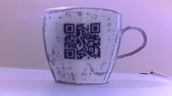
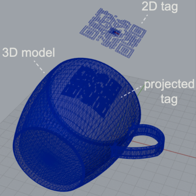
An interesting research project out of MIT shows that it’s possible to embed machine-readable labels into 3D printed objects using nothing more than an FDM printer and filament that is transparent to IR. The method is being called InfraredTags; by embedding something like a QR code or ArUco markers into an object’s structure, that label can be detected by a camera and interactive possibilities open up.

One simple proof of concept is a wireless router with its SSID embedded into the side of the device, and the password embedded into a different code on the bottom to ensure that physical access is required to obtain the password. Mundane objects can have metadata embedded into them, or provide markers for augmented reality functionality, like tracking the object in 3D.
How are the codes actually embedded? The process is straightforward with the right tools. The team used a specialty filament from vendor 3dk.berlin that looks nearly opaque in the visible spectrum, but transmits roughly 45% in IR.  The machine-readable label gets embedded within the walls of a printed object either by using a combination of IR PLA and air gaps to represent the geometry of the code, or by making a multi-material print using IR PLA and regular (non-IR transmitting) PLA. Both provide enough contrast for an IR-sensitive camera to detect the label, although the multi-material version works a little better overall. Sadly, the average mobile phone camera by itself isn’t sufficiently IR-sensitive to passively read these embedded tags, so the research used easily available cameras with no IR-blocking filters, like the Raspberry Pi NoIR.

The PDF has deeper details of the implementation for those of you who want to know more, and you can see a demonstration of a few different applications in the video, embedded below. Determining the provenance of 3D printed objects is a topic of some debate in the industry, and it’s not hard to see how technology like this could be used to covertly identify objects without compromising their appearance.

Continue reading “Invisible 3D Printed Codes Make Objects Interactive”

Label Your Shtuff!

Joshua Vasquez wrote a piece a couple of weeks ago about how his open source machine benefits greatly from having part numbers integrated into all of the 3D printed parts. It lets people talk exactly about which widget, and which revision of that widget, they have in front of them.

Along the way, he mentions that it’s also a good idea to have labels as an integrated part of the machine anywhere you have signals or connectors. That way, you never have to ask yourself which side is positive, or how many volts this port is specced for. It’s the “knowledge in the head” versus “knowledge in the world” distinction — if you have to remember it, you’ll forget it, but if it’s printed on the very item, you’ll just read it.

I mention this because I was beaten twice in the last week by this phenomenon, once by my own hand costing an hour’s extra work, and once by the hand of others, releasing the magic smoke and sending me crawling back to eBay.

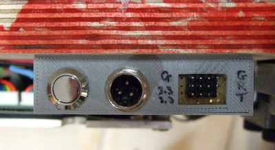
The first case is a 3D-printed data and power port, mounted on the underside of a converted hoverboard-transporter thing that I put together for last year’s Chaos Communication Congress. I was actually pretty proud of the design, until I wanted to reflash the firmware a year later.

I knew that I had broken out not just the serial lines and power rails (labelled!) but also the STM32 SWD programming headers and I2C. I vaguely remember having a mnemonic that explained how TX and RX were related to SCK and SDA, but I can’t remember it for the life of me. And the wires snake up under a heatsink where I can’t even trace them out to the chip. “Knowledge in the world”? I failed that, so I spent an hour looking for my build notes. (At least I had them.)

Then the smoke came out of an Arduino Mega that I was using with a RAMPS 1.4 board to drive a hot-wire cutting CNC machine. I’ve been playing around with this for a month now, and it was gratifying to see it all up and running, until something smelled funny, and took out a wall-wart power supply in addition to the Mega.

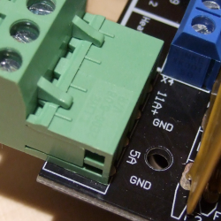
All of the parts on the RAMPS board are good to 36 V or so, so it shouldn’t have been a problem, and the power input is only labelled “5 A” and “GND”, so you’d figure it wasn’t voltage-sensitive and 18 V would be just fine. Of course, you can read online the tales of woe as people smoke their Mega boards, which have a voltage regulator that’s only good to 12 V and is powered for some reason through the RAMPS board even though it’s connected via USB to a computer. To be honest, if the power input were labelled 12 V, I still might have chanced it with 18 V, but at least I would have only myself to blame.

Part numbers are a great idea, and I’ll put that on my list of New Year’s resolutions for 2021. But better labels, on the device in question, for any connections, isn’t even going to wait the couple weeks until January. I’m changing that right now.