Retrotechtacular: The Deadly Shipmate

During World War II, shipboard life in the United States Navy was a gamble. No matter which theater of operations you found yourself in, the enemy was all around on land, sea, and air, ready to deliver a fatal blow and send your ship to the bottom. Fast forward a couple of decades and Navy life was just as hazardous but in a different way, as this Navy training film on the shipboard hazards of low-voltage electricity makes amply clear.

With the suitably scary title “115 Volts: A Deadly Shipmate,” the 1960 film details the many and various ways sailors could meet an untimely end, most of which seemed to circle back to attempts to make shipboard life a little more tolerable. The film centers not on the risks of a ship’s high-voltage installations, but rather the more familiar AC sockets used for appliances and lighting around most ships. The “familiarity breeds contempt” argument rings a touch hollow; given that most of these sailors appear to be in their 20s and 30s and rural electrification in the US was still only partially complete through the 1970s, chances are good that at least some of these sailors came from farms that still used kerosene lamps. But the point stands that plugging an unauthorized appliance into an outlet on a metal ship in a saltwater environment is a recipe for being the subject of a telegram back home.

The film shows just how dangerous mains voltage can be through a series of vignettes, many of which seem contrived but which were probably all too real to sailors in 1960. Many of the scenarios are service-specific, but a few bear keeping in mind around the house. Of particular note is drilling through a bulkhead and into a conduit; we’ve come perilously close to meeting the same end as the hapless Electrician’s Mate in the film doing much the same thing at home. As for up-cycling a discarded electric fan, all we can say is even brand new, that thing looks remarkably deadly.

The fact that they kept killing the same fellow over and over for each of these demonstrations doesn’t detract much from the central message: follow orders and you’ll probably stay alive. In an environment like that, it’s probably not bad advice.

Continue reading “Retrotechtacular: The Deadly Shipmate”

Measuring current draw of home shop tools

Using Homebrew Coils To Measure Mains Current, And Taking The Circuit Breaker Challenge

Like many hackers, [Matthias Wandel] has a penchant for measuring the world around him, and quantifying the goings-on in his home is a bit of a hobby. And so when it came time to sense the current flowing in the wires of his house, he did what any of us would do: he built his own current sensing system.

What’s that you say? Any sane hacker would buy something like a Kill-a-Watt meter, or even perhaps use commercially available current transformers? Perhaps, but then one wouldn’t exactly be hacking, would one? [Matthias] opted to roll his own sensors for quite practical reasons: commercial meters don’t quite have the response time to catch the start-up spikes he was interested in seeing, and clamp-on current transformers require splitting the jacket on the nonmetallic cabling used in most residential wiring — doing so tends to run afoul of building codes. So his sensors were simply coils of wire shaped to fit the outside of the NM cable, with a bit of filtering to provide a cleaner signal in the high-noise environment of a lot of switch-mode power supplies.

Fed through an ADC board into a Raspberry Pi, [Matthias]’ sensor system did a surprisingly good job of catching the start-up surge of some tools around the shop. That led to the entertaining “Circuit Breaker Challenge” part of the video below, wherein we learn just what it really takes to pop the breaker on a 15-Amp branch circuit. Spoiler alert: it’s a lot.

Speaking of staying safe with mains current, we’ve covered a little bit about how circuit protection works before. If you need a deeper dive into circuit breakers, we’ve got that too.

Continue reading “Using Homebrew Coils To Measure Mains Current, And Taking The Circuit Breaker Challenge”

A Peek Inside A Typical British Residential Power Panel

No matter what field you’re in, it’s interesting and instructive to find out how others practice it. That’s especially true with electrical distribution systems, where standards and practices differ from country to country and even between regions. This tour of a typical British residential electrical panel is a great example of the different ways that the same engineering problems can be solved, and the compromises that always attend any design.

We’re used to seeing [Big Clive] tearing interesting devices to bits, but rest assured that this electrical panel remains largely intact as it gives up its secrets. Compared to the distribution panels and circuit breakers common in North American residential construction, the British consumer unit is a marvel of neatness and simplicity. True, the unit on display hasn’t been put into service yet, and things will no doubt change once an electrician is through with it, but the fact that everything is DIN rail mounted is pretty cool. [Clive] explains a few of the quirks of the panel, such as the fact that what looks like a main breaker is in fact just an isolation switch, and that there are a pair of residual current devices (RCDs), which we call ground-fault circuit interrupters (GFCIs) in North America, that also don’t act as circuit breakers, despite appearances. A stout bus bar is provided to link the RCDs to adjacent circuit breakers, forming two groups that are separately protected from ground faults.

[Clive] notes with dismay that the lugs of the bus bar can actually be inserted behind the rising clamp terminal on the breaker, resulting in poor connections and overheating. Still, we wouldn’t mind some of these concepts brought to panels in North America, which we covered a bit in a discussion on circuit protection a while back.

Continue reading “A Peek Inside A Typical British Residential Power Panel”

Mains Power Supply For ATtiny Project Is Probably A Bad Idea

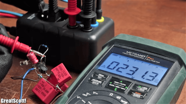
When designing a mains power supply for a small load DC circuit, there are plenty of considerations. Small size, efficiency, and cost of materials all spring to mind. Potential lethality seems like it would be a bad thing to design in, but that didn’t stop [Great Scott!] from exploring capacitive drop power supplies. You know, for science.

The backstory here is that [Great Scott!] is working on a super-secret ATtiny project that needs to be powered off mains. Switching power supplies are practically de rigueur for such applications, but compared to the intended microcontroller circuit they are actually quite large, and they’ve just been so done before. So in order to learn a thing or two, [Scott!] designed a capacitive dropper supply, where the reactance of the cap acts like a dropping resistor to limit the current. His first try was just a capacitor in series with an LED; this didn’t end well for the LED.

To understand why, he reverse-engineered a few low-current mains devices and found that practical capacitive droppers need a few more components, chiefly a series resistance to prevent inrush current from getting out of hand, but also a bridge rectifier and a zener to clamp things down. Wiring up all that resulted in a working capacitive dropper supply, but a the cost of as much real estate as a small switcher, and with the extra bonus of being potentially lethal if the power supply is plugged in the wrong way. Side note: we thought German line cords were polarized to prevent this, but apparently not? (Ed Note: Nope!)

As always, even when [Great Scott!]’s projects don’t exactly work out, like a suboptimal 3D-printed BLDC or why not to bother building your own DC-AC inverter, we enjoy the learning that results.

Continue reading “Mains Power Supply For ATtiny Project Is Probably A Bad Idea”

Adventures In Power Outage Hacking

The best type of power outage is no power outage, but they will inevitably happen. When they do, a hacker with a house full of stuff and a head full of ideas is often the person of the hour. Or the day, or perhaps the week, should the outage last long past the fun little adventure phase and become a nuisance or even an outright emergency.

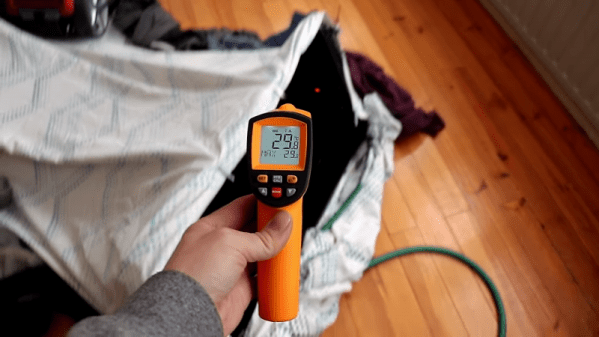
Such was the position that [FFcossag] found himself in at the beginning of January, when a freak storm knocked out power to his community on a remote island in the middle of the Baltic Sea. [FFcossag] documented his attempts to survive the eight-day outage in vlog form, and although each entry is fairly long, there’s a lot to be learned from his ordeal. His main asset was a wood cook stove in the basement of the house, which served as his heat source. He used a car radiator and a small water pump to get some heat upstairs – a battery bank provided the power for that, at least for a while. The system evolved over the outage and became surprisingly good at keeping the upstairs warm.

The power eventually came back on, but to add insult to injury, almost as soon as it did, the ground-source heat pump in the house went on the fritz. A little sleuthing revealed an open power resistor in the heat pump control panel, but without a replacement on hand, [FFcossag] improvised. Parts from a 30-year-old TV transmitter were close at hand, including a nice handful of power resistors. A small parallel network gave the correct value and the heat pump came back online.

All in all, it was a long, cold week for [FFcossag], but he probably fared better than his neighbors. Want to be as prepared for your next outage? Check out [Jenny]’s comprehensive guide.

Continue reading “Adventures In Power Outage Hacking”

Listening To Mains Power, Part 2

The electricity on the power grid wherever you live in the world will now universally come to you as AC. That is to say that it will oscillate between positive and negative polarity many times every second. The frequency of 50 or 60Hz just happens to be within the frequency range for human hearing. There’s a lot more than this fundamental frequency in the spectrum on the power lines though, and to hear those additional frequencies better you’ll have to do a little bit of signal processing.

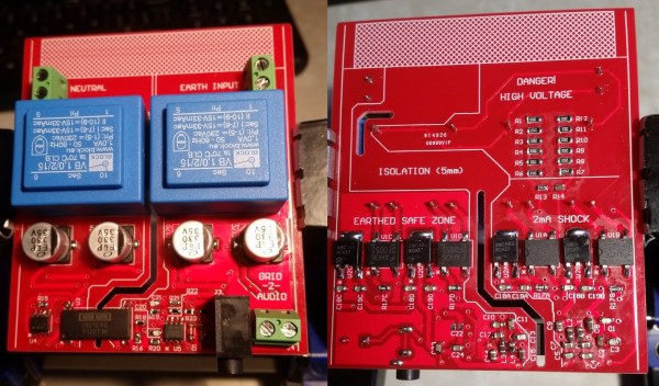
We first featured this build back when it was still in its prototyping phase, but since then it’s been completed and used successfully to find a number of anomalies on the local power grid. It takes inputs from the line, isolates them, and feeds them into MATLAB via a sound card where they can be analyzed for frequency content. It’s been completed, including a case, and there are now waterfall diagrams of “mystery” switching harmonics found with the device, plus plots of waveform variation over time. There’s also a video below that has these harmonics converted to audio so you can hear the electricity.

Since we featured it last, [David] also took some feedback from the comments on the first article and improved isolation distances on his PCB, as well as making further PCB enhancements before making the final version. If you’ve ever been curious as to what you might find on the power lines, be sure to take a look at the updates on the project’s page.

Continue reading “Listening To Mains Power, Part 2”

A Look At Liquid Dielectrics

One evening quite a few years ago, as I was driving through my hometown I saw the telltale flashing lights of the local volunteer fire department ahead. I passed by a side road where all the activity was: a utility pole on fire. I could see smoke and flames shooting from the transformer and I could hear the loud, angry 60 Hz buzzing that sounded like a million hornet nests. As I passed, the transformer exploded and released a cloud of flaming liquid that rained down on the road and lawns underneath. It seemed like a good time to quit rubbernecking and beat it as fast as I could.

I knew at the time that the flaming liquid was transformer oil, but I never really knew what it was for or why it was in there. Oil is just one of many liquid dielectrics that are found in a lot of power distribution equipment, from those transformers on the pole to the big capacitors and switchgear in the local substation. Liquid dielectrics are interesting materials that are worth taking a look at.

Continue reading “A Look At Liquid Dielectrics”