Adam Savage with a box ceramic blocks

A Savage Discussion Of Measurement And Accuracy

It’s commonly said that the great thing about standards is that there are so many of them. Of course, that’s talking about competing standards. But there’s another kind of standard that you want a lot of: Measurements. Without standard measurements, the Industrial Revolution wouldn’t have been facilitated to the extent it was. The illustrious [Adam Savage] takes a deep dive into the art of measurement in the video below the break, and if you have 45 minutes to spare, you will not be disappointed.

We don’t want to give away any big spoilers, but [Adam] starts out with things we can all relate to if we’ve done any kind of measuring for accuracy: measuring between the given lines on a standard tape measure. From there he goes into calipers and other tools for measurement.

Then, out come the Big Guns. The ceramic blocks so flat that… well you’ll just have to watch it. But the discussion goes deep into nanometers, microns, and jeweled movements.

Whether you’re a machinist or a garage hacker with nothing more than a stick welder and an angle grinder at your disposal, or anywhere in between in any segment of being a maker, this video is for you. [Adam]’s enthusiasm is off the charts in this diatribe, and we have to admit- it’s contagious! We’ve never been so excited about measuring things.

Of course, if you need to measurement tool, you can just build a measurement tool. It’s all subjective, after all.

Continue reading “A Savage Discussion Of Measurement And Accuracy”

A Simple Touch Probe Made With Basic Tools

Six points of contact detect any displacement.

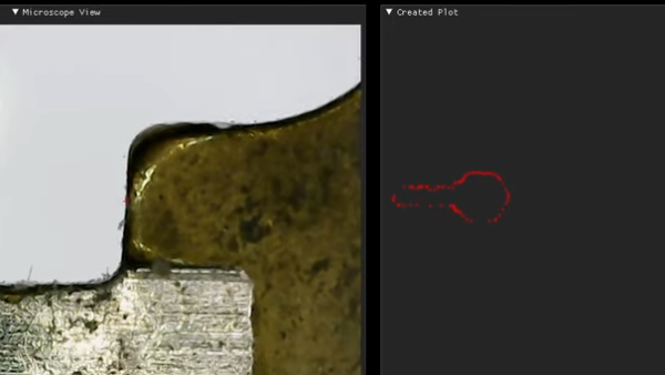
LinuxCNC contributor and machining enthusiast [Andy Pugh] is certainly not afraid to try making specialised tools to see how well they work out, and this time he’s been busy making a touch probe (video, embedded below) for checking the accuracy of machining operations and general measuring applications.

These things are not cheap, since they are essentially ‘just’ a switch with a long probe, But, as with anything specialised and machined with tight tolerances, you can understand why they cost what they do.

After inspecting and spending some time reverse-engineering such a unit, [Andy] then proceeded to grab some PEEK bar he had lying around and chuck it into the lathe (get it?). He notes Delrin would be more cost effective for those wishing to reproduce this, but as long as you have the ability to machine it and it’s non-conductive, there are many other options you could try.

Using no special tools other than a collet block (like this one) all the angled holes and slots were made with ease, with the help of a specially 3D-printed mount for the vise. A nice, simple approach, we think!

[Andy] tested the repeatability of the probe, mounted over his CNC-converted Holbrook lathe, reporting a value of 1 um, which seems rather good. Centering of the probe tip within the probe body was off a bit, as you’d expect for something made practically by hand, but that is less of a problem as it would seem, as it results in a fixed offset that can be compensated for in software. Perhaps the next version will have some adjustability to dial that out manually?

The whole assembly is formed from two plastic parts, a handful of ground-finished hardened steel pins, and a big spring. The only part remotely special is an off-the-shelf probe tip. During the electrical hookup, you may notice the use of a self-fluxing verowire pen, which was something this scribe didn’t know existed and has already placed an order for!

The reference 3D model for the design is shared from [Andy]’s Autodesk Drive for your viewing pleasure.

Of course, this isn’t the first DIY touch probe we’ve seen, here’s one for example, and over on Hackaday.IO, here’s an attempt to make one using a piezoelectric transducer.

Continue reading “A Simple Touch Probe Made With Basic Tools”

Gladys West Modelled The Earth So That We Can Have GPS

The name Gladys West is probably unfamiliar, but she was part of creating something you probably use often enough: GPS. You wouldn’t think a child who grew up on a sharecropping farm would wind up as an influential mathematician, but perhaps watching her father work very hard for very little and her mother working for a tobacco company made her realize that she wanted more for herself. Early on, she decided that education was the way out. She made it all the way to the Naval Surface Warfare Center.

While she was there she changed the world with — no kidding — mathematics. While she didn’t single-handedly invent satellite navigation, her work was critical to the systems we take for granted today.

Continue reading “Gladys West Modelled The Earth So That We Can Have GPS”

Vintage Monochromator Makes Monochromatic Light, Mechanically

A monochromator is an optical instrument that permits only a narrow selection of wavelengths to be transmitted from a source, and the particular model [Doug] obtained renders visual light monochromatic by way of a mechanically-adjusted system of mirrors and diffraction gratings that allows only the selected wavelength to pass. The big dial is how the operator selects the desired wavelength, and is labeled in ‘mu’ (or milli-micro), but [Doug] helpfully points out the more modern term for that is nanometers.

LCD monitor viewed through a monochromator set to pass red wavelength only, showing that images remain intact.

How does it work? Light enters the device via an opening at the base, and only the selected wavelength exits from the top. The dial’s range is from 450 nm to 640 nm (representing violet-blue to red), which [Doug] demonstrates by shining a white LED flashlight into the unit and showing how only green, red, or blue will exit from the top depending on the setting of the dial.

An interesting side note is that with this particular device, images can be rendered monochromatic but otherwise remain intact. [Doug] demonstrates this by viewing a small section of his LCD monitor through the device, as shown in the photo he managed to capture.

It’s an interesting piece of vintage equipment that shows what is possible with passive optical components and a clever mechanical design. These devices are therefore entirely manually-operated tools (at least until someone sticks a stepper motor to the adjustment dial to create an automated scanner, that is.)

You Can’t Fix What You Can’t Measure

Last year, as my Corona Hobby™, I took up RC plane flying. I started out with discus-launched gliders, and honestly that’s still my main love, but there’s only so much room for hackery in planes that are designed to be absolutely minimum weight and maximum performance; these are the kind of planes that notice an extra half gram in the tail. So I’ve also built a few crude workhorse planes — the kind of things that you could slap a 60 g decade-old GoPro on and it won’t even really notice. Some have ended their lives in trees, but most have been disassembled and reincarnated — the electronics live on in the next body.

The journey has been really fun. I’ve learned about aerodynamics, gotten an excuse to put together a 4-axis hot-wire CNC styrofoam cutter, and covered everything in sight with carbon fiber tow, which is cheaper than you might think but makes the plane space-age. My current workhorse has bolted on an IMU, GPS, and a minimal Ardupilot setup, though I have yet to really put it through its paces. What’s holding me back is the video link — it just won’t work reliably further than a few hundred meters, and I certainly don’t trust it to get out of line-of-sight.

My suspicion is that the crappy antennas I have are holding me back, which of course is an encouragement to DIY, but measuring antennas in the 5.8 GHz band is tricky. I’d love to just be able to buy one of the cheap vector analyzers that we’ve covered in the past — anyone can make an antenna when they can see what they’re doing — but they top out at 2.4 GHz or lower. No dice. I’m blind in 5.8 GHz.

Of course, I do have one way in, and that’s tapping into the received signal strength indicator (RSSI) of a dedicated 5.8 GHz receiver, and just testing antennas out in practice, but that only gives a sort of loose better-worse indication. More capacitance or more inductance? Plates closer together or further apart? Try it out and see, I guess, but it’s time-consuming.

Moral of the story: don’t take measurement equipment for granted. Imagine trying to build an analog circuit without a voltmeter, or to debug something digital without a logic probe. Sometimes the most important tool is the one that lets you see the problem in the first place.

Your PC Sound Card As A Sensor Input

The commoditised PC is the most versatile tool many of us will own, and since it has been around for a very long time it is also something that can be found for free or very cheaply if the latest components aren’t a concern. It’s not without limitations though, while it’s designed for expansion it no longer has any ports that can easily be repurposed as GPIOs for reading sensors. A solution for some sensors comes courtesy of [Ruslan Nagimov], who shows us how the PC sound card can become a measurement interface.

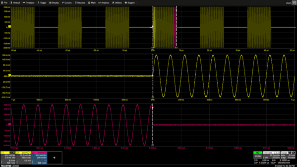
The idea is that simple resistive or capacitive sensors can be read through their AC characteristics by sending out a sine wave on one channel of the card and reading the result on the other from a divider circuit. He goes extensively into the code, both for the resistive example and for reactive components, and we can see that it forms a handy extension to the PC capabilities.

We’re sure this technique will find applications for some readers, but it interests us for another platform. Measurement using a mobile phone’s audio jack doesn’t have an inspiring history, but perhaps this could be used as well for mobile sensors.

Budget-Friendly Bend Sensor Deforms With Precision

We’re pretty familiar with budget resistor-based bend sensors at this point, but this sensor is in a totally different class. Instead of relying on resistive elements, [Useok Jeong] and [Kyu-Jin Cho] devised a bend sensor that relies on geometric properties of the sensor itself. The result is a higher-fidelity measuring device made from a pretty widely available collection of stock parts.

We’ll admit, calling this device a bend sensor might be a bit of a stretch, so let’s dig into some of the operating principles. What we’re actually measuring is the accumulated angle, the sum of all the curvature deformations along the length of the sensing element. The sensor is made of 3 main pieces: an outer extension spring-based wire sheath; a flexible, tensioned inner wire core that’s fixed at one end; and a small displacement sensor that measures the length changes in the wire’s free end. The secret ingredient to making this setup work is a special property of the outer wire sheath or spring guide. Here, the spring guide actually resists being compressed while being bent.  Because the inner radius of the bend remains a constant length, the center wire core is forced to elongate. With the excess wire spooled up at the sensor base, we simply measure how much we collected, apply some math, and get a resulting angle! What’s more, the folks behind this trick also demonstrate that the length and angle relationship is linear with an R-square of 0.9969.

One of the best parts about this sensor is how reproducible it seems from from a modest collection of stock parts. Spring guide (aka: extension spring) is available from McMaster-Carr and DR Templeman, and that flexible core might be readily substituted with some wire rope.

It’s not everyday that new topologies for bend sensors pop into the world, let alone linear ones. To learn more, the folks behind the project have kindly made their research paper open access for your afternoon reading enjoyment. (Bring scratch paper!) Finally, if you’re looking for other bend-related sensors, have a look at this multi-bend measurement setup.

Continue reading “Budget-Friendly Bend Sensor Deforms With Precision”