About Right

I really enjoyed reading Anne Ogborn’s piece on making simple DIY measurement devices for physical quantities like force, power, and torque. It is full of food for thought, if you’re building something small with motors and need to figure out how to spec them out.
A Push Stick

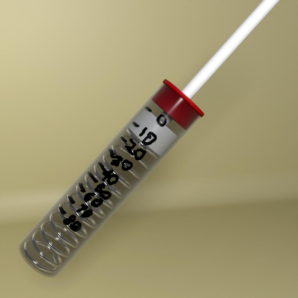
Aside from a few good examples, what I really took home from this piece is how easy it can be to take approximate measurements. Take the push stick, which is a spring-loaded plunger in a transparent barrel. You use it to measure force by, well, squeezing the spring and reading off how far it deflects. That’s obvious, but the real trick is in calibration by pushing it into a weighing scale and marking divisions on the barrel. That quickly and easily turns “it’s pressing this hard” into an actual numerical force measurement.

The accuracy and precision of the push stick are limited by the quality of your scale and the fineness of the pen tip that you use to mark the barrel. But when you’re just looking to choose among two servo motors, this kind of seat-of-the-pants measure is more than enough to buy the right part. Almost any actual measurement is better than a wild-ass guess, so don’t hold yourself to outrageous standards or think that improvised quantitative measurement devices aren’t going to get the job done.

Al Williams quoted a teacher of his as saying that the soul of metrology is “taking something you know and using it to find something you don’t know”, and that sums up this piece nicely. But it’s also almost a hacker manifesto: “take something you can do and use it to do something that you can’t (yet)”.

Got any good measurement hacks you’d like to share?
Ask Hackaday: Do You Calibrate Your Instruments?

Like many of you, I have a bench full of electronic instruments. The newest is my Rigol oscilloscope, only a few years old, while the oldest is probably my RF signal generator that dates from some time in the early 1950s. Some of those instruments have been with me for decades, and have been crucial in the gestation of countless projects.

If I follow the manufacturer’s recommendations then just like that PAT tester I should have them calibrated frequently. This process involves sending them off to a specialised lab where their readings are compared to a standard and they are adjusted accordingly, and when they return I know I can trust their readings. It’s important if you work in an industry where everything must be verified, for example I’m certain the folks down the road at Airbus use meticulously calibrated instruments when making assemblies for their aircraft, because there is no room for error in a safety critical application at 20000 feet.

But on my bench? Not so much, nobody is likely to face danger if my frequency counter has drifted by a few Hz. Continue reading “Ask Hackaday: Do You Calibrate Your Instruments?”

You Can’t Make What You Can’t Measure

What’s the most-used tool on your bench? For me, it’s probably a multimeter, although that’s maybe a tie with my oscilloscope. Maybe after that, the soldering iron and wire strippers, or my favorite forceps. Calipers must rate in there somewhere too, but maybe a little further down. Still, the top place, and half of my desert-island top-10, go to measuring gear.

That’s because any debugging, investigation, or experimentation always starts with getting some visibility on the problem. And the less visible the physical quantity, the more necessary to tool. For circuits, that means figuring out where all the voltages lie, and you obviously can’t just guess there. A couple months ago, I was doing some epoxy and fiberglass work, and needed to draw a 1/2 atmosphere vacuum. That’s not the kind of quantity you can just eyeball. You need the right measurement tool.

A few weeks ago, I wrote about my disappointment in receiving a fan that wouldn’t push my coffee beans around in the homemade roaster. How could I have avoided this debacle? By figuring out the pressure differential needed and buying a fan that’s appropriately rated. But I lacked pressure and flow meters.

Now that I think about it, I could have scavenged the pressure meter from the fiberglassing rig, and given that a go, but with the cheap cost of sensors and amplifiers, I’ll probably just purpose-build something. I’m still not sure how I’ll measure the flow; maybe I’ll just cheese out and buy a cheap wind-speed meter.

When people think of tools, they mostly think of the “doers”: the wrenches and the hammers of this world. But today, let’s all raise a calibrated 350 ml glass to the “measurers”. Without you, we’d be wandering around in the dark.

Hackaday Prize 2023: AC Measurements Made Easy

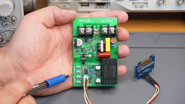
When working on simple DC systems, a small low-cost multimeter from the hardware store will get the job done well enough. Often they have the capability for measuring AC, but this is where cheap meters can get tripped up. Unless the waveform is a perfect sinusoid at a specific frequency, their simple algorithms won’t be able to give accurate readings like a high-quality meter will. [hesam.moshiri] took this as a design challenge, though, and built an AC multimeter to take into account some of the edge cases that come up when working with AC circuits, especially when dealing with inductive loads.

The small meter, an upgrade from a previous Arduino version that is now based on the ESP32, is capable of assessing root mean square (RMS) voltage, RMS current, active power, power factor, and energy consumption after first being calibrated using the included push buttons. Readings are given via a small OLED screen and have an accuracy rate of 0.5% or better. The board also includes modern design considerations such as galvanic isolation between the measurement side of the meter and the user interface side, each with its own isolated power supply.  The schematics and bill-of-materials are also available for anyone looking to recreate or build on this design.

With the project built on an easily-accessible platform like the ESP32, it would be possible to use this as a base to measure other types of signals as well. Square and triangle waves, as well as signals with a large amount of harmonics or with varying frequencies, all need different measurement techniques in order to get accurate readings. Take a look at this classic multimeter to see what that entails.

Continue reading “Hackaday Prize 2023: AC Measurements Made Easy”

Checking Belt Tension Gets Easier For (Some) Prusa 3D Printers

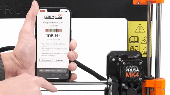
Belts on a 3D printer should be tight enough, but not too tight. That can be an iffy thing to get right for someone who lacks familiarity with CNC platforms. Prusa Research aims to make it a bit easier with a web app that can measure tension via your mobile phone’s microphone and diagnose belt tightness, at least for their MK4 and XL printers.

Using different tools to analyze belt tightness (including belt acoustics) have been tried in the past with mixed results, but this is a pretty focused approach that aims to give exact guidance for specific printer models. It’s pretty useful to provide someone with a reliable go/no-go number, after all.

What happens to a printer if a belt’s tension is not right? Well, there’s actually a pretty forgiving range within which the printer will mostly work fine, but not as well as it could be. Loose belts can have novices chasing other problems, and overly-tightened belts definitely put extra strain on parts. It’s one of those things that’s worth a little extra work to get right.

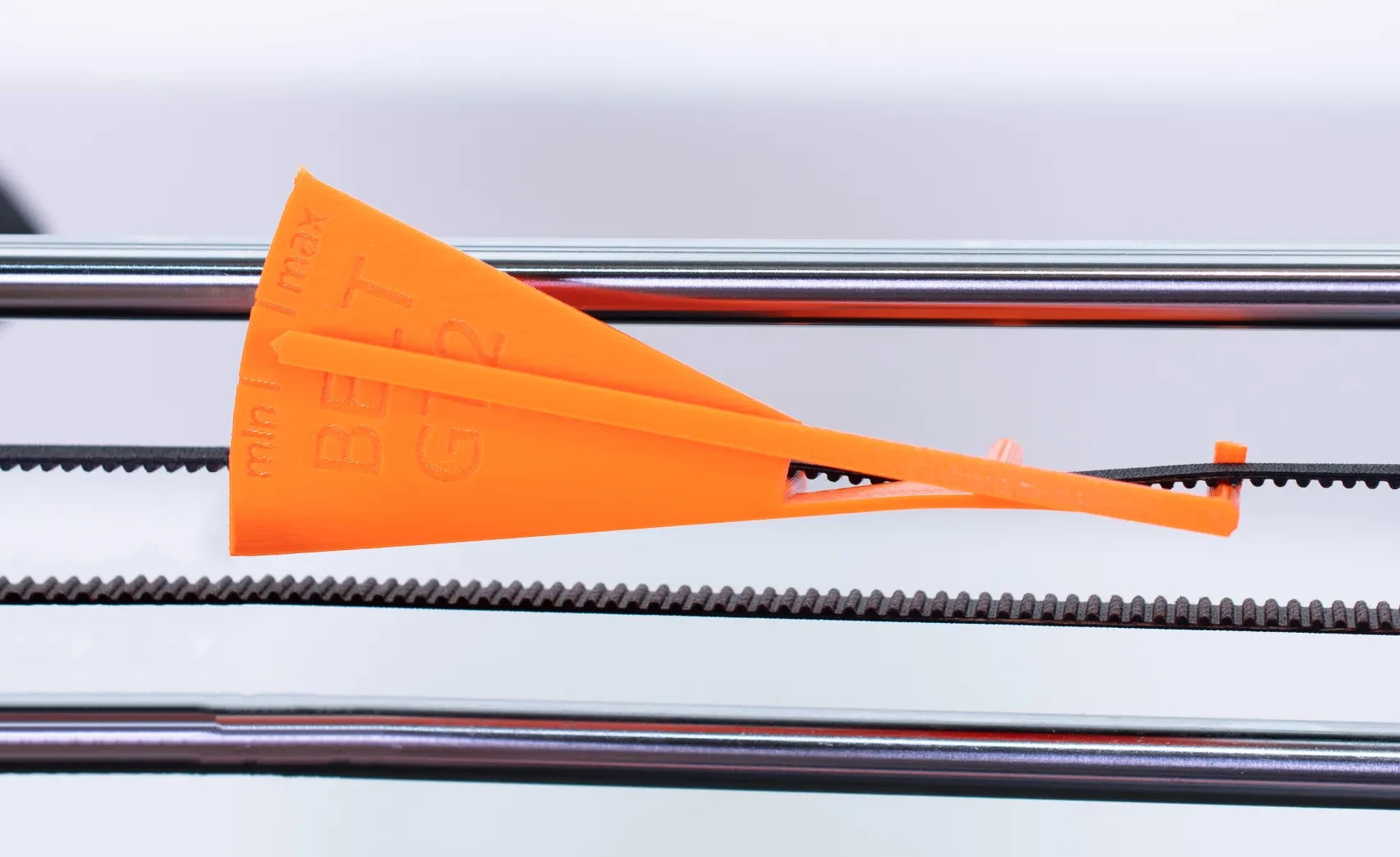
3D printable tension meter is a different option for Prusa MK3 and Mini printers, if one has some Prusament PETG to print it in.

Everything about belt tension for Prusa printers is covered in their documentation, but did you know there’s also neat 3D printable tension meter for Prusa MK3 and Mini printers? It’s meant to be printed in Prusament PETG (printing in other materials may have different results) but it’s a pretty neat idea for a tool.

If you have a Prusa MK4 or XL and want to try their new method, go here and allow access to your device’s microphone. Then select a printer model and an axis to test. Gently strum the upper part of the belt (avoid touching the bottom belt in the process) and watch live results telling you whether the belt is too tight, too loose, or just right. Prusa have a video demonstrating the process, also embedded below.

Continue reading “Checking Belt Tension Gets Easier For (Some) Prusa 3D Printers”

A Deep Dive On Battery Life

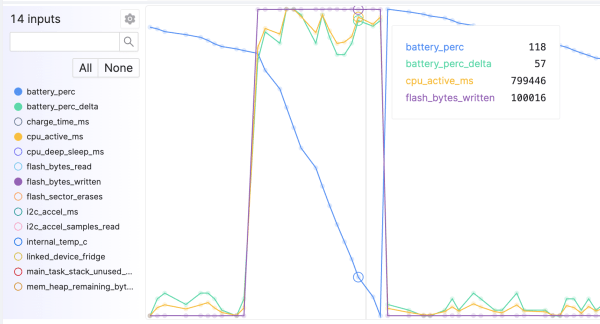
There are all kinds of old wives’ tales surrounding proper battery use floating around in the popular culture. Things like needing to fully discharge a battery every so often, unplugging devices when they’re fully charged, or keeping batteries in the fridge are all examples that have some kernel of truth to them but often are improperly applied. If you really want to know the truth about a specific battery, its behavior, and its features, it helps to dig in and actually take some measurements directly like [Tyler] has done with a vast array of embedded batteries in IoT devices.

[Tyler] is a firmware engineer by trade, so he is deeply familiar with this type of small battery. Battery performance can change dramatically under all kinds of scenarios, most important among them being temperature. But even the same type of battery can behave differently to others that are otherwise identical, which is why it’s important to have metrics for the batteries themselves and be able to measure them to identify behaviors and possible problems. [Tyler] has a system of best practices in place for monitoring battery performance, especially after things like firmware upgrades since small software changes can often have a decent impact on battery performance.

While working with huge fleets of devices, [Tyler] outlines plenty of methods for working with batteries, deploying them, and making sure they’re working well for customers. A lot of it is extremely useful for other engineers looking to develop large-scale products like this but it’s also good knowledge to have for those of us rolling out our own one-off projects that will operate under battery power. After all, not caring for one’s lithium batteries can have disastrous consequences.

High Voltage Power Supply From USB

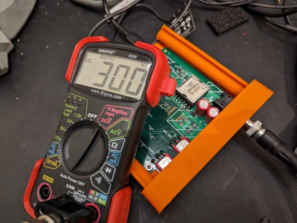
Those who work in different spaces may have different definitions of the term “high voltage”. For someone working on the GPIO pins of a Raspberry Pi it might be as little as 5 volts, someone working on a Tesla coil might consider that to be around 20 kV, and an electrical line worker might not reference something as HV until 115 kV. What we could perhaps all agree on, though, is that getting 300 volts out of a USB power supply is certainly a “high voltage” we wouldn’t normally expect to see in that kind of context, but [Aylo6061] needed just such a power supply and was eventually able to create one.

In this case, the high voltages will eventually be used for electrophoresis or electrowetting. But before getting there, [Aylo6061] has built one of the safest looking circuits we’ve seen in recent memory. Every high voltage part is hidden behind double insulation, and there is complete isolation between the high and low voltage sides thanks to a flyback converter. This has the benefit of a floating ground which reduces the risk of accidental shock. This does cause some challenges though, as voltage sensing on the high side is difficult while maintaining isolation, so some clever tricks were implemented to maintain the correct target output voltage.

The control circuitry is based around an RP2040 chip and is impressive in its own right, with USB isolation for the data lines as well. Additionally the project code can be found at its GitHub page. Thanks to a part shortage, [Aylo6061] dedicated an entire core of the microprocessor to decoding digital data from the high voltage sensor circuitry. For something with a little less refinement, less safety, and a much higher voltage output, though, take a look at this power supply which tops its output voltage around 30 kV.