If you have ever ventured into the world of motor vehicles you may be familiar with a dynamometer, possibly as a machine to which your vehicle is taken for that all-important printout that gives you bragging rights (or not) when it comes to its ability to lay down rubber. A dynamometer is essentially a variable load for a rotating shaft, something that converts the kinetic energy from the shaft into heat while measuring the power being transferred.
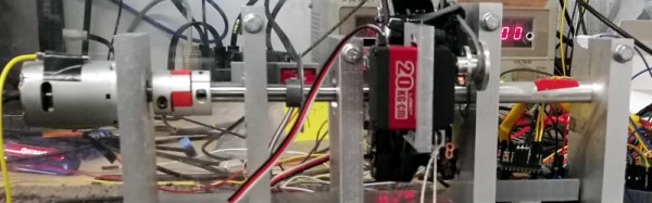
Most of us will never have the chance to peer inside our local dyno, so a term project from a group of Cornell students might be something of interest. They’ve built a dynamometer for characterising small electric motors, and since their work is part of their degree courses, their documentation of it goes into great detail.
Their dynamometer takes the form of a shaft driving a stainless steel disc brake upon which sit a pair of calibers mounted on a fixed shaft that forms a torsion bar. The whole is mounted in a sturdy stainless steel chassis, and is studded with sensors, a brace of strain gauges and a slotted disc rotation sensor. It’s not the largest of dynamometers, but you can learn about these devices from their work just as they have.
This is a project sent to us by [Bruce Land], one of many from his students that have found their way to these pages. His lectures on microcontrollers are very much worth a look.
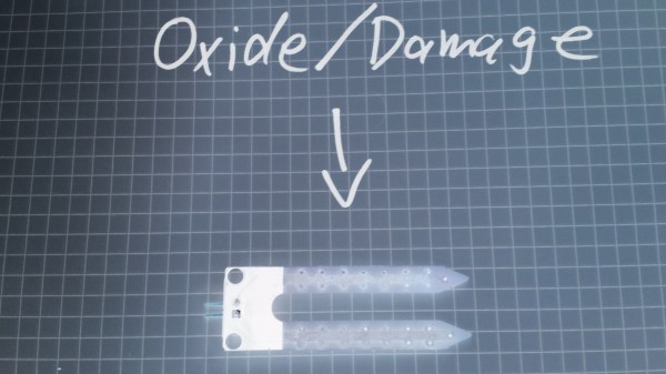
If you compulsively search online for inexpensive microcontroller add-ons, you will see soil moisture measurement kits. [aka] built a greenhouse with a host of hacked hardware including lights and automatic watering. What caught our attention among all these was Step 5 in their instructions where [aka] explains why the cheap soil sensing probes aren’t worth their weight in potting soil. Even worse, they may leave vacationers with a mistaken sense of security over their unattended plants.
The sensing stakes, which come with a small amplifier, work splendidly out of the box, but if you recall, passing current through electrodes via moisture is the recipe for electrolysis and that has a pretty profound effect on metal. [Aka] shows us the effects of electrolysis on these probes and mentions that damaged probes will cease to give useful information which could lead to overworked pumps and flooded helpless plants.
There is an easy solution. Graphite probes are inexpensive to make yourself. Simply harvest them from pencils or buy woodless pencils from the art store. Add some wires and hold them with shrink tube, and you have probes which won’t fail you or your plants.
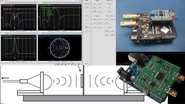
Instrumentation has progressed by leaps and bounds in the last few years, however, the fundamental analysis techniques that are the foundation of modern-day equipment remain the same. A network analyzer is an instrument that allows us to characterize RF networks such as filters, mixers, antennas and even new materials for microwave electronics such as ceramic capacitors and resonators in the gigahertz range. In this write-up, I discuss network analyzers in brief and how the DIY movement has helped bring down the cost of such devices. I will also share some existing projects that may help you build your own along with some use cases where a network analyzer may be employed. Let’s dive right in.
Network Analysis Fundamentals
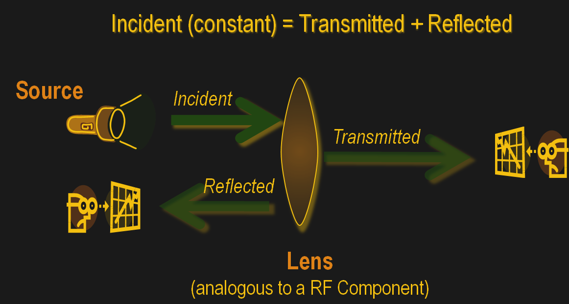
As a conceptual model, think of light hitting a lens and most of it going through but part of it getting reflected back.
The same applies to an electrical/RF network where the RF energy that is launched into the device may be attenuated a bit, transmitted to an extent and some of it reflected back. This analysis gives us an attenuation coefficient and a reflection coefficient which explains the behavior of the device under test (DUT).
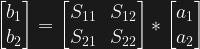
Of course, this may not be enough and we may also require information about the phase relationship between the signals. Such instruments are termed Vector Network Analysers and are helpful in measuring the scattering parameters or S-Parameters of a DUT.
The scattering matrix links the incident waves a1, a2 to the outgoing waves b1, b2 according to the following linear equation: .
The equation shows that the S-parameters are expressed as the matrix S, where and denote the output and input port numbers of the DUT.
This completely characterizes a network for attenuation, reflection as well as insertion loss. S-Parameters are explained more in details in Electromagnetic Field Theory and Transmission Line Theory but suffice to say that these measurements will be used to deduce the properties of the DUT and generate a mathematical model for the same.
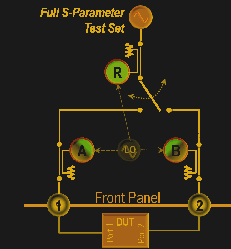
General Architecture
As mentioned previously, a simple network analyzer would be a signal generator connected and a spectrum analyzer combined to work together. The signal generator would be configured to output a signal of a known frequency and the spectrum analyzer would be used to detect the signal at the other end. Then the frequency would be changed to another and the process repeats such that the system sweeps a range of frequencies and the output can be tabulated or plotted on a graph. In order to get reflected power, a microwave component such as a magic-T or directional couplers, however, all of this is usually inbuilt into modern-day VNAs. Continue reading “Network Analysers: The Electrical Kind”→
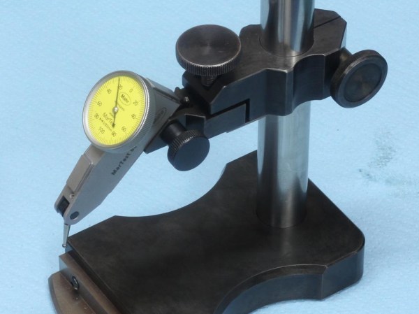
He was looking enviously at the squareness comparator that [Tom Lipton] had made when somone on Instagram posted a photo of the comparator they use every day. [Stefan] loved the design and set out to build one of his own. He copied it shamelessly, made a set of drawings, and got to work.
[Stefan]’s videos are always a trove of good machine shop habits and skills. He always shows how being careful, patient, and doing things the right way can result in really astoundingly precise work out of a home machine shop. The workmanship is beautiful and his knack for machining is apparent throughout. We chuckled at one section where he informed the viewer that you could break a tap on the mill when tapping under power if you bottom out. To avoid this he stopped at a distance he felt was safe: 0.5 mm away.
The construction and finishing complete, [Stefan] shows how to use the comparator at the end of the video, viewable after the break.
Measuring length is a pain, and it’s all the fault of Imperial measurements. Certain industries have standardized around either Imperial or metric, which means that working on projects across multiple industries generally leads to at least one conversion. For everyone outside the last bastion of Imperial units, here’s a primer on how we do it in crazy-land.
Definitions
The basic unit of length measurement in Imperial units is the inch. twelve inches make up one foot, three feet make up one yard, and 5,280 feet (or 1,760 yards) make up a mile. Easy to remember, right?
Ironically, an inch is defined in metric as 25.4 millimeters. You can do the rest of the math for exact lengths, but in general, three feet is just shy of a meter, and a mile is about a kilometer and a half. Generally in Imperial you’ll see lots of mixed units, like a person’s height is 6’2″ (that’s shorthand for six feet, two inches.) But it’s not consistent, it’s English; the only consistency is that it’s always breaking its own rules. You wouldn’t say three yards, two feet, and six inches; you’d say 11 1/2 feet. If it was three yards, one foot, and six inches, though, you’d say 3 1/2 yards. There’s no good rule for this other than try to use nice fractions as often as you can.
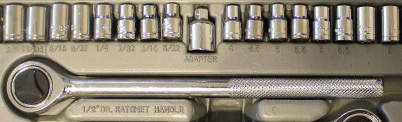
Users of Imperial units love fractions, especially when it comes to parts of an inch or mile. You’ll frequently find drill bits in fractions of an inch, which can be extremely frustrating when you are trying to do math in your head and figure out if a 17/64″ bit is bigger than a 1/4″ bit (hint, yes, it’s 1/64″ bigger).
A socket wrench set in Imperial fractions on the left and metric on the right. Metric is so much easier.
If it wasn’t hard enough already, there came the thousandth of an inch. As the machine age was getting better and better, and parts were getting smaller and more precise, there came a need for more accurate measurements than 1/64 inch. Development of appropriate tools for measuring such fine resolution was critical as well. You can call a 1/8″ bit a .125″ bit, and that means 125 thousandths of an inch. People didn’t like to wrap their mouths around that whole word, though, so it was reduced to “thou.” Others used the latin root for thousand, “mil.” To summarize, a mil is the equivalent of a thou, which is one thousandth of an inch. It should not be confused with a millimeter. It takes about 40 mils to make 1 millimeter. Also, the plural of mil is mils, and the plural of thou is thou.
Tools
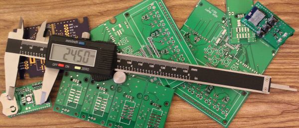
Outside calipers for measuring the outer dimensionBy Glenn McKechnie (Own work) [GFDL, CC-BY-SA-3.0 or CC BY-SA 2.5-2.0-1.0], via Wikimedia CommonsMeasuring length is done with a variety of tools, from GPS for long distances, to tape measures for feet/meters, and rulers for inches/centimeters. When it comes to very small measurements, the caliper is the tool of choice. This is the kind of tool that should be in everyone’s toolbox. Initially it started with the inside caliper and outside caliper, which were separate tools used to measure lengths. The Vernier caliper combined the two, added a depth meter and a couple other handy features, and gave machinists an all-around useful tool for measuring. Just like the slide rule, though, as soon as digital options became available, they took over. The digital caliper can usually switch modes between decimal inches, fractional inches, and metric.
Every industry has picked a different convention. Plastic sheets are usually measured in mils for thin stuff and millimeters or fractions of an inch for anything greater than 1/32″. Circuit boards combine units in every way imaginable, sometimes combining mils for trace width and metric for board dimensions, with the thickness of the copper expressed in ounces. (That’s not even a unit of length! It represents the amount of copper in one square foot of area and 1 oz is equivalent to 1.4mil.) Most of the time products designed outside of the U.S. are in metric units, while U.S. products are designed in either. When combining different industries, though, the difference in standards gets really annoying. For example, order 1/8″ plexiglass, and you may get 3mm plexiglass instead. Sure the difference is only .175mm (7 thou), but that difference can cause big problems for pieces that are press fit or when making finger joints on boxes, so it’s important that when sourcing components, you not only verify the unit, but if it’s a normal unit for that industry and it’s not just being rounded.
Often you can tell with what primary unit a product is designed with only a few measurements of a caliper. Find a dimension and see if it’s a nice round number in metric. If it’s not, switch it to imperial, and watch how quickly it snaps to a nice number.
Moving forward
Use metric if you can. The vast majority of the world does it. When you are sending designs overseas for production they will convert to metric (though they are used to working in both). It does take time to get used to it (especially when you are dealing with thou/mils), but your temporary discomfort will turn to relief when your design doesn’t crash into the Mars (or more realistically when you don’t have to pull out the Dremel and blade to get your parts to fit together).
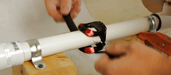
Physics gives us the basic tools needed to understand the universe, but turning theory into something useful is how engineers make their living. Pushing on that boundary is the subject of this week’s Fail of the Week, wherein we follow the travails of making a working magnetic flowmeter (YouTube, embedded below).
Theory suggests that measuring fluid flow should be simple. After all, sticking a magnetic paddle wheel into a fluid stream and counting pulses with a reed switch or Hall sensor is pretty straightforward, right? In this case, though, [Grady] of Practical Engineering starts out with a much more complicated flow measurement modality – electromagnetic detection. He does a great job of explaining Faraday’s Law of Induction and how a fluid can be the conductor that moves through a magnetic field and has a measurable current induced in it. The current should be proportional to the velocity of the fluid, so it should be a snap to whip up a homebrew magnetic flowmeter, right? Nope – despite valiant effort, [Grady] was never able to get a usable signal out of the noise in his system.
The theory is sound, his test rig looks workable, and he’s got some pretty decent instrumentation. So where did [Grady] go wrong? Could he clean up the signal with a better instrumentation amp? What would happen if he changed the process fluid to something more conductive, like salt water? By his own admission, electrical engineering is not his strong suit – he’s a civil engineer by trade. Think you can clean up that signal? Let us know in the comments section.
One of the most ingenious developments in test and measuring tools over the last few years is the Mooshimeter. That’s a wireless, two-channel multimeter that can measure voltage and current simultaneously. If you’ve ever wanted to look at the voltage drop and power output on a souped up electrified go-kart, the Mooshimeter is the tool for you.
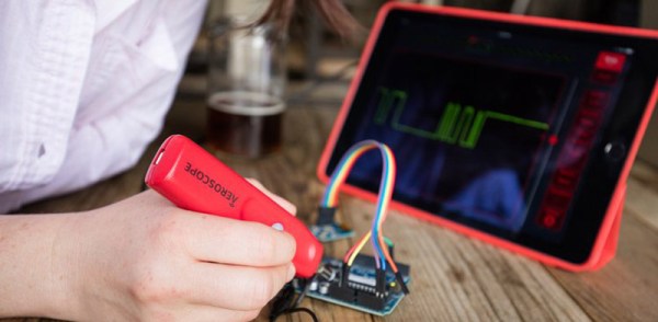
A cheap, wireless multimeter was only the fevered dream of a madman a decade ago. We didn’t have smartphones with Bluetooth back then, so any remote display would cost much more than the multimeter itself. Now this test and measurement over Bluetooth is bleeding over into the rest of the electronics workbench with the Aeroscope, a wireless Bluetooth oscilloscope.
[Alexander] and [Jonathan], the devs for the Aeroscope got the idea for this device while debugging a mobile robot. The robot would work on the bench, but in the field the problem would reappear. The idea for a wireless troubleshooting tool was born out of necessity.
The specs for the Aeroscope are about equal to the quite capable ‘My First Oscilloscope’ Rigol DS1052E. Analog bandwidth is 100MHz, sample rate is 500 Msamples/second, and the memory depth is 10k points. Resolution per division is 20mV to 10V, and the Aeroscope “Deluxe Package” that includes a few leads, tip, clip, USB cable, and case is about the same price as the Rigol 1052E. The difference, of course, is that the Aeroscope is a single channel, and wireless. That’s fairly impressive for two guys who aren’t a team of Rigol engineers.
As is the case with all Bluetooth test and measurement devices, the proof is in the app. Right now, the Aeroscope only supports iOS 9 devices, but according to the crowdfunding campaign, Android support is coming. Since the device is Open Source, you can always bang something out in Python if you really need to.
While this is a crowdfunding campaign, it’s hosted on Crowd Supply. Crowd Supply isn’t Indiegogo or Kickstarter; there are people at Crowd Supply vetting projects. The campaign still has a month to go, but the first few pledges are putting the Aeroscope right on track to a successful campaign.
 .
.
![Outside calipers for measuring the outer dimensionBy Glenn McKechnie (Own work) [GFDL, CC-BY-SA-3.0 or CC BY-SA 2.5-2.0-1.0], via Wikimedia Commons](https://hackaday.com/wp-content/uploads/2016/07/outsidecalipers.jpg?w=400)