Power Meter

Solar Panel System Monitoring Device Using Arduino

[Carl] recently upgraded his home with a solar panel system. This system compliments the electricity he gets from the grid by filling up a battery bank using free (as in beer) energy from the sun. The system came with a basic meter which really only shows the total amount of electricity the panels produce. [Carl] wanted to get more data out of his system. He managed to build his own monitor using an Arduino.

The trick of this build has to do with how the system works. The panel includes an LED light that blinks 1000 times for each kWh of electricity. [Carl] realized that if he could monitor the rate at which the LED is flashing, he could determine approximately how much energy is being generated at any given moment. We’ve seen similar projects in the past.

Like most people new to a technology, [Carl] built his project up by cobbling together other examples he found online. He started off by using a sketch that was originally designed to calculate the speed of a vehicle by measuring the time it took for the vehicle to pass between two points. [Carl] took this code and modified it to use a single photo resistor to detect the LED. He also built a sort of VU meter using several LEDs. The meter would increase and decrease proportionally to the reading on the electrical meter.

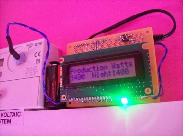
[Carl] continued improving on his system over time. He added an LCD panel so he could not only see the exact current measurement, but also the top measurement from the day. He put all of the electronics in a plastic tub and used a ribbon cable to move the LCD panel to a more convenient location. He also had his friend [Andy] clean up the Arduino code to make it easier for others to use as desired.

Water Tank Monitoring System Is Now Slug-Proof

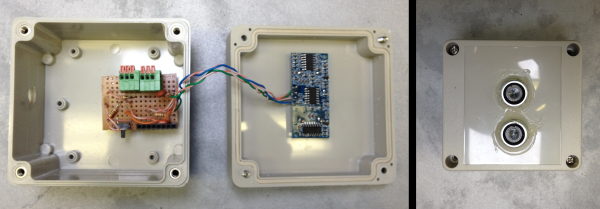
[Peter] is doing his part toward protecting the environment and conserving water. He’s built a rainwater collection system complete with an underground storage tank. Since he wanted to monitor the water level in the tank, he made a level indicating system. Everything was going well until one day out of nowhere it stopped working, only returning 0’s as the level. [Peter] took a look and found that I slug had made its way into the electronics enclosure and slimed up the traces on the PCB, causing short circuits.To fix the problem [Peter] decided to redesigned the system. This time it would be built into an all-weather electrical box. The system uses a standard hobby ultrasonic range finder to measure the distance from the top of the tank to the level of the water. Two holes cut into the electrical box allow the sender/receiver components to peek outside of the enclosure. Any gaps were then filled with sealant. [Peter] also added a thermistor to measure the temperature inside the tank.The sensor values are read by an Arduino and sent wirelessly to [Peter]’s computer via a pair of XBee’s and a second Arduino with an ethernet shield. The data are sent in 3 minute intervals and automatically stored in a MySQL database for quick reference of level and temperature trends. Now [Peter] can monitor his rain water remotely and adjust his usage habits accordingly. Want to read more about water tanks? Check out this overflow monitor system.

Tracking Power Usage With A Raspi

With tiny, Internet-connected computers everywhere these days, home automation is finally hitting it big. [Jelora] was looking for a few more home automation projects and realized his electric meter had a pair of ‘digital information outputs’. With a Raspberry Pi and a few bits of wire, he figured out how to read this digital output and put a log of his electricity consumption up on the web.

The digital output on [Jelora]’s meter is a bit odd; it’s 1200 bps, 7 bits per character, parity, with one stop bit. It’s also a 50 kHz AC signal for a binary ‘0’ and nothing for a binary ‘1’. To read this signal, [Jelora] is using a diode to throw out half the signal, a 6N138 optoisolator so the Pi isn’t connected directly to the meter, and a small cap to smooth out the signal. Simple, and it works.

This cleaned up signal is then connected to serial to USB chip and a PHP script scrapes the data every minute. The data received from the meter is stored in a data base along with a few other bits of information: if the meter is being charged peak or off-peak rates, and the price per kWh. All this is saved on an IDE hard drive (more reliable than the SD card, surprisingly), and a ‘electricity cost per day’ is plotted on a nifty graph and served up by the Raspberry Pi.

Power Meter

Electricity Usage Monitor Is Linked To Google Spreadsheets

If you want to make your home more energy-efficient, chances are you will need a way to monitor your electricity usage over time. There are off-the-shelf solutions for this of course, but hackers like us tend to do things our own way. Take [Karl] for example. He recently built himself a solution with only a few smart components. We’ve seen similar projects in the past, but none quite like this.

[Karl’s] home has a power meter that blinks an LED to indicate the current amount of used electricity in Watt-hours. He knew all he needed was a way to electronically detect the blinking LED and he’d be able to accurately track his usage without modifying the meter.

The primary components used in this project were a CC3200 development kit and a photoresistor module. The dev kit contained a WiFi module built-in, which allows the system to upload data to Google spreadsheets as well as sync the built-in clock with an accurate time source. The photoresistor module is used to actually detect the blinking LED on the power meter. Everything else is done easily with code on the dev kit.

THP Hacker Bio: Hackersbench


hackersbench-contestant-bio-banner

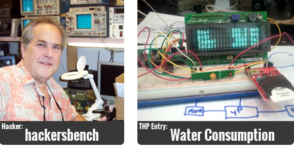
Remote sensing applications that make sense and cents? (sorry, couldn’t help ourselves) That’s what [hackersbench], aka [John Schuch], aka [@JohnS_AZ] is working on as his entry for The Hackaday Prize.

He received a multi-thousand-dollar water bill after having an underground pipe break and leak without knowing it. His idea will help you notice problems like this sooner. But if you actually have a way to capture data about your own water use you also have a tool to help encourage less wasteful water use habits. We wanted to learn more about the hacker who is working on this project. [John’s] answers to our slate of questions are after the break.

Continue reading “THP Hacker Bio: Hackersbench”

Gas, Water, And Electricity Monitoring

???????????????????????????????

From the look of this you can tell that [Jasper Sikken] has some pretty interesting stuff going on to monitor the utilities in his home. But it’s important to note that this is a rental home. So adding sensors to the gas, water, and electric meters had to be done without making any type of permanent changes.

The module above is his own base PCB which accepts an mbed board to harvest and report on usage. His electric meter has an LED that will flash for every Watt hour that is used. He monitors that with a light dependent resistor, crafting a clever way to fasten it to the meter using four magnets. The water meter has a disc that makes one revolution for each liter of water that passes through it. Half of the disc is reflective so he uses a photoreflective sensor to keep track of that. And finally the gas meter has a reflective digit on one of the wheels. The sensor tracks each time this digit passes by, signifying 10 liters of gas used. He also monitors temperature which we’re sure comes in handy when trying to make sense of the data.

[Thanks Stephen]


Water Tank Level Meter Prevents Overflow

roof-water-tank-level-meter

Most of the homes in the area where [Raikut] lives have tanks on the roof to hold water. Each is filled from a well using a pump, with gravity serving as a way to pressurize the home’s water supply. The system isn’t automatic and requires the home owner to manually switch the pump on and off. [Raikut] made this process a lot easier by designing an LED bar indicator to monitor the water level.

The sensor is very simple. Each LED is basically its own circuit controlled by a transistor and a few resistors. A 5V signal is fed from 7805 linear regulator into the tank. The base of each transitor is connected to an insulated wire, each extending different depths in the tank. As the water rises it completes the circuit, illuminating the LED.

[Raikut] is conservation minded and built a buzzer circuit which is activated by the LED indicating the highest water level. If someone walks away from the pump switch while it’s filling the alarm will sound as it gets to the top and they can turn it off before it wastes water.

[via Reddit]