Valentine Heart

Animated LED Valentine Heart

With only a week left until Valentine’s day, [Henry] needed to think on his feet. He wanted to build something for his girlfriend but with limited time, he needed to work with what he had available. After scrounging up some parts and a bit of CAD work, he ended up with a nice animated LED Valentine heart.

[Henry] had a bunch of WS2812 LEDs left over from an older project. These surface mount LED’s are very cool. They come in a small form factor and include red, green, and blue LEDs all in a single package. On top of that, they have a built-in control circuit which makes each LED individually addressable. It’s similar to the LED strips we’ve seen in the past, only now the control circuit is built right into the LED.

Starting with the LEDs, [Henry] decided to build a large animated heart. Being a stickler for details, he worked out the perfect LED placement by beginning his design with three concentric heart shapes. The hearts were plotted in Excel and were then scaled until he ended up with something he liked. This final design showed where to place each LED.

The next step was to design the PCB in Altium Designer. [Henry’s] design is two-sided with large copper planes on either side. He opted to make good use of the extra copper surface by etching a custom design into the back with his girlfriend’s name. He included a space for the ATMega48 chip which would be running the animations. Finally, he sent the design off to a fab house and managed to get it back 48 hours later.

After soldering all of the components in place, [Henry] programmed up a few animations for the LEDs. He also built a custom frame to house the PCB. The frame includes a white screen that diffuses and softens the light from the LEDs. The final product looks great and is sure to win any geek’s heart. Continue reading “Animated LED Valentine Heart”

Watt Meter Build Walks You Through Power Measurement Basics

You almost never hear of a DC Watt Meter – one just does some mental math with Volts and Amps at the back of one’s head. An AC Watt Meter, on the other hand, can by pretty useful on any workbench. This handy DIY Digital AC Watt Meter not only has an impressive 30A current range, but is designed in a hand-held form factor, making it easy to carry around.

The design from Electro-Labs provides build instructions for the hardware, as well as the software for the PIC micro-controller at its heart. A detailed description walks you through the schematic’s various blocks, and there’s also some basics of AC power measurement thrown in for good measure. The schematic and board layout are done using SolaPCB – a Windows only free EDA tool which we haven’t heard about until now. A full BoM and the PIC code round off the build. On the hardware side, the unit uses MCP3202 12 bit ADC converters with SPI interface, making it easy to hook them up to the micro-controller. A simple resistive divider for voltage and an ACS-712  Hall Effect-Based Linear Current Sensor IC are the main sense elements. Phase calculations are done by the micro-controller. The importance of isolation is not overlooked, using opto-isolators to keep the digital section away from the analog. The board outline looks like it has been designed to fit some off-the-shelf hand-held plastic enclosure (if you can’t find one, whip one up from a 3D printer).

Although the design is for 230V~250V range, it can easily be modified for 110V use by changing a few parts. Swap the transformer, change the Resistive voltage divider values, maybe some DC level shifting, and you’re good to go. The one feature that would be a nice upgrade to this meter would be Energy measurements, besides just Power. For an inside look at how traditional energy meters work, head over to this video where [Ben Krasnow] explains KiloWatt Hour Meters


Tetris

Arduino Tetris On A Multiplexed LED Matrix

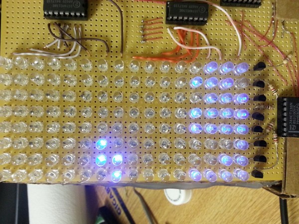
[Alex] needed a project for his microcomputer circuits class. He wanted something that would challenge him on both the electronics side of things, as well as the programming side. He ended up designing an 8 by 16 grid of LED’s that was turned into a game of Tetris.

He arranged all 128 LED’s into the grid on a piece of perfboard. All of the anodes were bent over and connected together into rows of 8 LED’s. The cathodes were bent perpendicularly and forms columns of 16 LED’s. This way, if power is applied to one row and a single column is grounded, one LED will light up at the intersection. This method only works reliably to light up a single LED at a time. With that in mind, [Alex] needed to have a very high “refresh rate” for his display. He only ever lights up one LED at a time, but he scans through the 128 LED’s so fast that persistence of vision prevents you from noticing. To the human eye, it looks like multiple LED’s are lit up simultaneously.

[Alex] planned to use an Arduino to control this display, but it doesn’t have enough outputs on its own to control all of those lights. He ended up using multiple 74138 decoder/multiplexer IC’s to control the LED’s. Since the columns have inverted outputs, he couldn’t just hook them straight up to the LED’s. Instead he had to run the signals through a set of PNP transistors to flip the logic. This setup allowed [Alex] to control all 128 LED’s with just seven bits, but it was too slow for him.

His solution was to control the multiplexers with counter IC’s. The Arduino can just increment the counter up to the appropriate LED. The Arduino then controls the state of the LED using the active high enable line from the column multiplexer chip.

[Alex] wanted more than just a static image to show off on his new display, so he programmed in a version of Tetris. The controller is just a piece of perfboard with four push buttons. He had to work out all of the programming to ensure the game ran smoothly while properly updating the screen and simultaneously reading the controller for new input. All of this ran on the Arduino.

Can’t get enough Tetris hacks? Try these on for size.

Ice Clock

Binary Clock Fit For Queen Elsa’s Ice Palace

When life gives you lemons, you make lemonade. When life gives you freezing cold temperatures and a yard full of snow, you make binary clocks out of ice. At least that’s what [Dennis] does, anyway.

[Dennis’] clock is made from several cylindrical blocks of ice stacked on top of one another. There are six columns of ice blocks. The blocks were made by pouring water into empty margarine containers and freezing them. Once they were frozen, [Dennis] bore a 5/16″ hole into the bottom of each block to house an LED. Wires ran from the LEDs back into the drainage port of a cooler.

The cooler housed the main electronics. The LED controller board is of [Dennis’] own design. It contains six TLC59282 chips allowing for control of up to 96 LEDs. Each chip has its output lines running to two RJ45 connectors. [Dennis] couldn’t just use one because one of the eight wires in the connector was used as a common power line. The main CPU is an Arduino. It’s hooked up to a DS3234 Real Time Clock in order to keep accurate time. The oscillator monitors temperature in order to keep accurate time even in the dead of winter. Continue reading “Binary Clock Fit For Queen Elsa’s Ice Palace”

Drums Anywhere!

The students over at Cornell’s School of Electrical and Computer Engineering have been hard at it again with their senior projects. This time, it’s the very tiny and portable drumset dubbed Drums Anywhere by its creators [Shiva Rajagopal] and [Richard Quan]. Since there are other highly portable instruments like roll-up pianos, they suppose there should be a portable drum kit that actually sounds like drums, and this ECE duo have hit the metaphorical and physical drum on the head… except that this project doesn’t actually use physical drums to make sound.

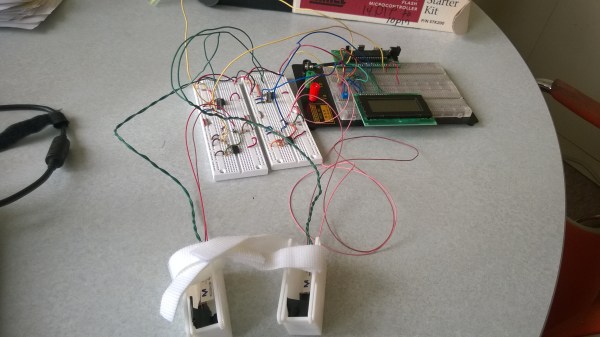
The project consists of two 3D-printed box-like sensors with velcro straps that can be attached to any drumstick-shaped object that might be lying around. Inside the box is a flex sensor and a tiny microphone which report the “beats” to a microcontroller when they strike another object.

On the software side, there are two sampled sounds stored in the microcontroller but they plan to add more sounds in the future. The microcontroller outputs sound to a pair of speakers, and the sensors are sensitive to force, so the volume can range from almost inaudible all the way up to [John Bonham]-style booms. This could also be theoretically expanded to include more than two “beat boxes” for extra sounds, or be wireless. The options are virtually limitless, although the team notes that they are limited by the number of interrupts and ADC converters on their particular microcontroller, an ATmega1284.

This is another interesting take on a having drumset without the drums, and definitely expands the range of what a virtual drum set can do. It’s also great to see interesting projects coming from senior design classes! Be sure to check out the video after the break.

Continue reading “Drums Anywhere!”

USB Cap

Never Forget Your USB Stick Again

USB sticks are very handy. They are a very portable and relatively inexpensive means of storing data. Possibly the most annoying part about using one of these devices is when you inevitable leave it behind somewhere by accident. This is especially true if it contains sensitive information. [Eurekaguy] feels your pain, and he’s developed a solution to the problem.

[Eurekaguy] designed a custom cap for USB sticks that beeps approximately every minute after the USB stick has been plugged in for five minutes. The cap is 3D printed and then slightly modified with four 1mm holes. Two wires are routed between these holes to make contact points for the VCC and GND pins of the USB stick.

The beep circuit is comprised of a tiny PIC12F629 microcontroller along with a couple of other supporting components. The circuit is wired together dead bug style to conserve space. Three AG5 batteries power the circuit. A small piezo speaker provides the repeating beep to remind you to grab your USB stick before you walk away from the computer.

[Thanks Irish]

Boxing Trainer

Boxing Trainer Uses DIY Force Sensors

A team of Cornell students have designed and built their own electronic boxing trainer system. The product of their work is a game similar to Whack-A-Mole. There are five square pads organized roughly into the shape of a human torso and head. Each pad will light up based on a pre-programmed pattern. When the pad lights up, it’s the player’s job to punch it! The game keeps track of the player’s accuracy as well as their reaction time.

The team was trying to keep their budget under $100, which meant that off the shelf components would be too costly. To remedy this, they designed their own force sensors. The sensors are basically a sandwich of a few different materials. In the center is a 10″ by 10″ square of ESD foam. Pressed against it is a 1/2″ thick sheet of insulating foam rubber. This foam rubber sheet has 1/4″ slits cut into it, resulting in something that looks like jail bars. Sandwiching these two pieces of foam is fine aluminum window screen. Copper wire is fixed the screen using conductive glue. Finally, the whole thing is sandwiched between flattened pieces of corrugated cardboard to protect the screen.

The sensors are mounted flat against a wall. When a user punches a sensor, it compresses. This compression causes the resistance between the two pieces of aluminum screen to change. The resistance can be measured to detect a hit. The students found that if the sensor is hit harder, more surface area becomes compressed. This results in a greater change in resistance and can then be measured as a more powerful hit. Unfortunately it would need to be calibrated depending on what is hitting the sensor, since the size of the hitter can throw off calibration.

Each sensor pad is surrounded by a strip of LEDs. The LEDs light up to indicate which pad the user is supposed to hit. Everything is controlled by an ATMEGA 1284p microcontroller. This is the latest in a string of student projects to come out of Cornell. Make sure to watch the demonstration video below. Continue reading “Boxing Trainer Uses DIY Force Sensors”