[Afroman’s] latest video shows you how to add reverse voltage protection with minimal power loss. At some point, one of your electronic concoctions will turn out to be very useful. You want to make sure that a battery plugged in the wrong way, or a polarity mistake with your bench PSU doesn’t damage that hardware. It’s easy enough to plop in a diode for protection, but as [Afroman] points out, that wastes power in the form of heat when the circuit is working correctly. His solution is to add a P channel MOSFET which only allows power to flow when the polarity of the source voltage is correct.
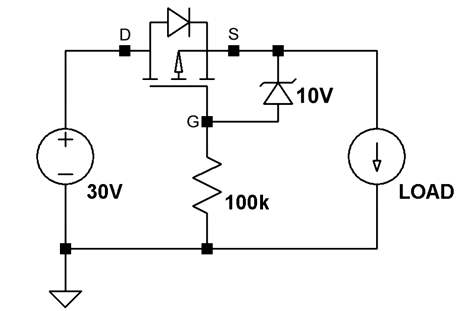
The schematic above shows the P-FET on the high side of the circuit. The gate is hooked to ground, allowing current to move across the DS junction when the battery is connected. This design also uses a clamping diode to keep the gate voltage within a safe range. But there are P-FETs out there that wouldn’t need that diode or resistor. This method wastes ten times less power than a simple diode would have.
We’ve embedded the video after the break where [Afroman] shares the math and reasoning behind his component choices.