One Stepper Plus A Whole Bunch Of Magnets Equals A Unique Seven-Segment Display

Sometimes the cost of simplicity is extra complexity. It seems counterintuitive, but it seems to be true. And this single-motor mechanical seven-segment display seems to be a perfect example of this paradox.

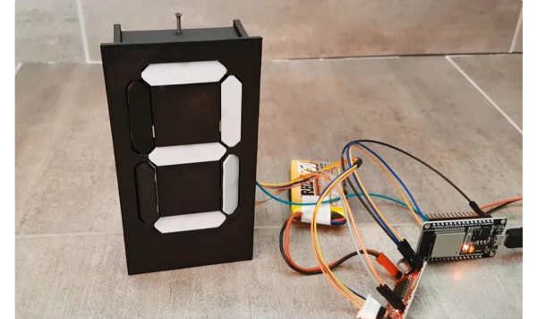
On second thought, [aeropic]’s mechanism isn’t really all that mechanically complicated, but there sure was a lot of planning and ingenuity that went into it. The front has a 3D-printed bezel with the familiar segment cutouts, each of which is fitted with a pivoting segment, black on one side and white on the other.

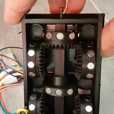
Behind the bezel is a vertical shaft with three wheels, one behind each horizontal segment, and a pair of horizontal shafts, each with two wheels behind each vertical segment. The three shafts are geared to turn together by a single stepper in the base. Each wheel has ten magnets embedded in the outer circumference, with the polarity oriented to flip the segment in front of it to the right orientation for the current digit. It’s probably something that’s most easily understood by watching the video below.

We’ve seen quite a few of these mechanical seven-segment displays lately — this cam-and-servo mechanism comes to mind. We love them all, of course, but the great thing about [aeropic]’s display is how quiet it is — the stepper is mostly silent, and the segments make only a gentle clunk when they flip. It’s very satisfying.

Continue reading “One Stepper Plus A Whole Bunch Of Magnets Equals A Unique Seven-Segment Display”

Magnetic Bearings Put The Spin On This Flywheel Battery

[Tom Stanton] is right about one thing: flywheels make excellent playthings. Whether watching a spinning top that never seems to slow down, or feeling the weird forces a gyroscope exerts, spinning things are oddly satisfying. And putting a flywheel to work as a battery makes it even cooler.

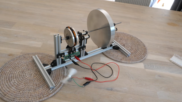
Of course, using a flywheel to store energy isn’t even close to being a new concept. But the principles [Tom] demonstrates in the video below, including the advantages of magnetically levitated bearings, are pretty cool to see all in one place. The flywheel itself is just a heavy aluminum disc on a shaft, with a pair of bearings on each side made of stacks of neodymium magnets. An additional low-friction thrust bearing at the end of the shaft keeps the systems suitably constrained, and allows the flywheel to spin for twelve minutes or more.

[Tom]’s next step was to harness some of the flywheel’s angular momentum to make electricity. He built a pair of rotors carrying more magnets, with a stator of custom-wound coils sandwiched between. A full-wave bridge rectifier and a capacitor complete the circuit and allow the flywheel to power a bunch of LEDs or even a small motor. The whole thing is nicely built and looks like a fun desk toy.

This is far from [Tom]’s first flywheel rodeo; his last foray into storing mechanical energy wasn’t terribly successful, but he has succeeded in making flywheels fly, one way or another.

Continue reading “Magnetic Bearings Put The Spin On This Flywheel Battery”

Wood Enclosure Lends Warmth To This DIY Ribbon Microphone

We love it when someone takes an idea they’ve seen on Hackaday and runs with it, taking it in a new and different direction. That’s pretty much what we’re here for, after all, and it’s pretty gratifying to see projects like this wooden ribbon microphone come to life.

Now, we’re not completely sure that [Maya Román] was inspired by our coverage of [Frank Olson]’s homage to the RCA Model 44 studio mic rendered in walnut veneer, but we’re going to pat ourselves on the back here anyway. The interesting thing with [Maya]’s build is that she chose completely different materials and design styles for her project. Where [Frank] built as much of his mic from wood as possible, [Maya] was fine with a mixed media approach — CNC-milled plywood for the case and stand, laser-cut acrylic for the ribbon motor frame, and 3D-printed pieces here and there as needed. The woven brass cloth used as a windscreen is a nice detail; while the whole thing looks — and sounds — great, we think it would be even better with a coat of dark stain to contrast against the brass, as well as a nice glossy coat of polyurethane.

The video below shows the whole design and build process, which was a final project for [Maya]’s audio production class this semester at college. Here’s hoping that it got as good a grade as we would give it.

Continue reading “Wood Enclosure Lends Warmth To This DIY Ribbon Microphone”

Magnetic Angle Sensor Mods Make Encoder Better For Blasting

Most of the hacks we see around these parts have to do with taking existing components and cobbling them together in interesting new ways. It’s less often that we see existing components gutted and repurposed, but when it happens, like with this reimagined rotary encoder, it certainly grabs our attention.

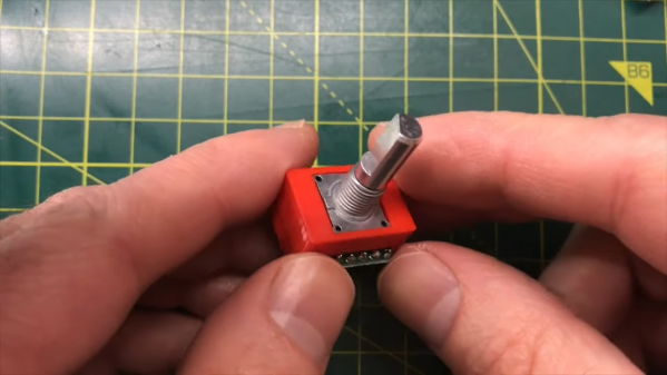
You may recall [Chris G] from his recent laser-based Asteroids game. If not you should really check it out — the build was pretty sweet. One small problem with the build was in the controls, where the off-the-shelf rotary encoder he was using didn’t have nearly enough resolution for the job. Rather than choosing a commodity replacement part, [Chris] rolled his own from the mechanical parts of the original encoder, like the shaft and panel bushing, and an AS5048A sensor board. The magnetic angle sensor has 14 bits of resolution, and with a small neodymium ring magnet glued to the bottom of the original shaft, the modified encoder offers far greater resolution than the original contact-based encoder.

The sensor breakout board is just the right size for this job; all that [Chris] needed to do to get the two pieces together was to 3D-print a small adapter. We have to admit that when we first saw this on Hackaday.io, we failed to see what the hack was — the modified part looks pretty much like a run-of-the-mill encoder. The video below shows the design and build process with a little precision rock blasting.

Continue reading “Magnetic Angle Sensor Mods Make Encoder Better For Blasting”

Aesthetic DIY Bluetooth Speakers

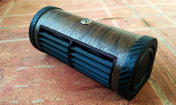
DIY Bluetooth speaker projects are always a staple here at Hackady. In our latest feature of DIY audio builds, we have [Patrick’s] vinyl cylindrical speaker.

He found a pretty inexpensive Bluetooth audio amplifier on AliExpress. However, the amplifier module oddly enough had a few missing components that were critical to its operation, so he had to do a little bit of re-work. Not something you generally expect to do when you purchase a pre-made module, but he was certainly up to the task.

He noticed the board amp module was missing a battery protection circuit even though there was space on the board laid out for those components (maybe an older board revision?). To remedy this problem, he added his own battery protection circuit to prevent any unwanted catastrophes. Secondly, he noticed a lot of distortion at high volumes and figured that some added capacitance on the power supply would help fix the distortion. Luckily, that did the trick.

Finally, and not quite a mistake on the manufacturer’s part this time, but an improvement [Patrick] needed for his own personal use. He wanted the amp module’s board-level LED indicator to be visible once the enclosure was fitted around the electronics. So, he used the built-in status trigger as a digital signal for a simple transistor circuit powering a much brighter ring LED that could be mounted onto the enclosure. That way, he could utilize the firmware for triggering the board-level status indicator for his own ring LED without any software modifications to the amp module.

Now, all that was left was to construct the enclosure he had 3D-printed and fit all the electronics in their place. We’ve gotten pretty used to the always impressive aesthetics of [Patrick’s] designs, having covered a project of his before, and this build is certainly no exception. Great job!

While you’re here, take a look at some other DIY Bluetooth speaker projects on Hackaday.

Continue reading “Aesthetic DIY Bluetooth Speakers”

Magnetic Couplings Make This Lego Submarine Watertight

Although you’d be hard-pressed to tell in some areas, it’s summer in the northern hemisphere, which always seems to bring out the projects that require a swimming pool for adequate testing. The [Brick Experiment Channel]’s latest build, a submersible made almost entirely from Lego, is one such project and has us pining for weather that makes a dip sensible rather than suicidal.

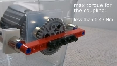
The sub featured in the video below is a significant improvement over the “Sub in a Jug” approach the [Brick Experiment Channel] favored for version 1. Rather than starting with a vessel specifically designed not to hold water, the hull for this vessel is an IKEA food container, with a stout glass body and a flexible lid with silicone seals. And instead of penetrating the hull for driveshafts and attempting to seal them, this time around he built clever magnetic couplings.

The couplings transmit torque from the motors on the inside to gears and props on the outside. And where the first version used a syringe-pump ballast tank to control the depth, this one uses vertical thrusters. The flexible lid proved to be a problem with that scheme, since it tended to collapse as the depth increased, preventing the sub from surfacing. That was solved with some Lego bracing and adjustment of the lead shot ballast used to keep the sub neutrally buoyant.

This looks like a ton of summer fun, and even if you don’t have Legos galore to work with, it could easily be adapted to other materials. There are a ton of other fun [BEC] Lego builds to check out, some of which we’ve covered, including a Lego drone and a playing card shooter.

Continue reading “Magnetic Couplings Make This Lego Submarine Watertight”

Simple Demo Shows The Potential Of Magnetic Gears

We’ve probably all used gears in our projects at one time or another, and even if we’re not familiar with the engineering details, the principles of transmitting torque through meshed teeth are pretty easy to understand. Magnetic gears, though, are a little less intuitive, which is why we appreciated stumbling upon this magnetic gear drivetrain demonstration project.

[William Fraser]’s demo may be simple, but it’s a great introduction to magnetic gearing. The stator is a block of wood with twelve bolts to act as pole pieces, closely spaced in a circle around a shaft. Both ends of the shaft have rotors, one with eleven pairs of neodymium magnets arranged in a circle with alternating polarity, and a pinion on the other side of the stator with a single pair of magnets. When the pinion is spun, the magnetic flux across the pole pieces forces the rotor to revolve in the opposite direction at a 12:1 ratio.

Watching the video below, it would be easy to assume such an arrangement would only work for low torque applications, but [William] demonstrated that the system could take a significant load before clutching out. That could even be a feature for some applications. We’ve got an “Ask Hackaday” article on magnetic gears if you want to dive a little deeper and see what these interesting mechanisms are good for.

Continue reading “Simple Demo Shows The Potential Of Magnetic Gears”