[Facelessloser] is interested in glanceable information. Glancable devices are things like your car’s dashboard, your wristwatch, or widgets on a smartphone lockscreen. The glanceable information distribution system in this case is rpi_status, [facelessloser’s] entry in the Enlightened Raspberry Pi Contest.
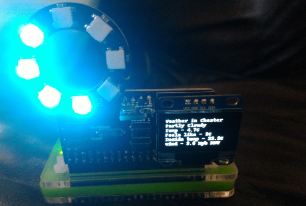
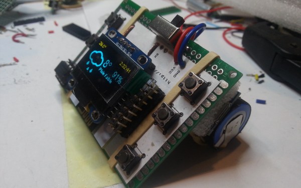
[Facelessloser] coupled a ring of eight WS2812 RGB LEDs with a small OLED screen managed by a the common ssd1306 controller. Since he was rolling his own board for this project, [faceless] some buttons and a BMP180 temperature sensor. Going with popular parts like this meant libraries like the Pimoroni unicorn hat library for the WS2812 were readily available.
A simple display like this can show just about anything – from status of a nightly software build, to traffic along your morning commute. [Facelessloser] is using it for weather data. His data source is Weather Underground’s API. Weather information is displayed on the OLED. The WS2812’s display the temperature. A single blue light means cold. The ring fills as the temperature warms up. After eight degrees of blue, the color changes to orange, followed by red.
Check out the video after the break for a short demo of the board.
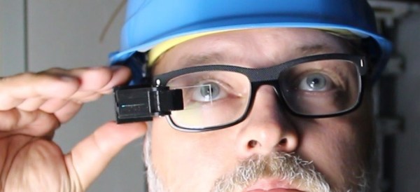


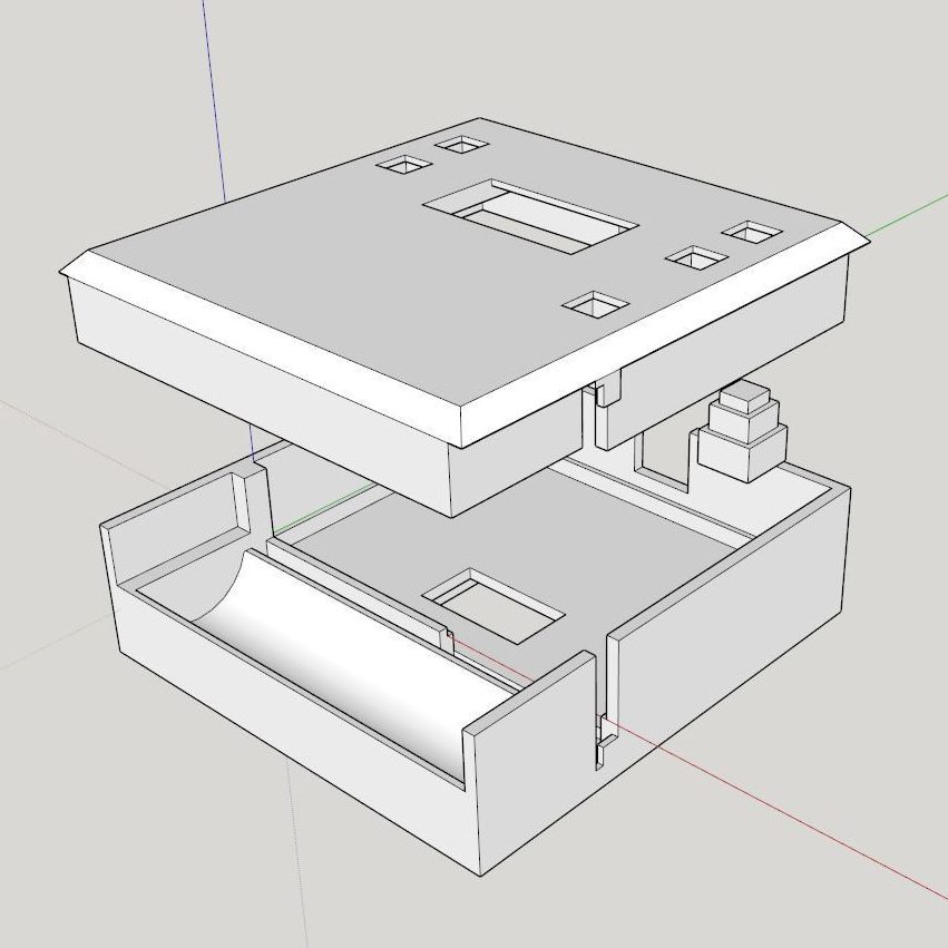


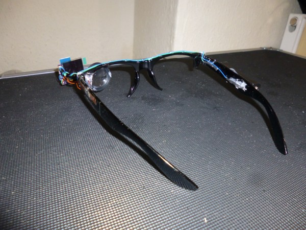
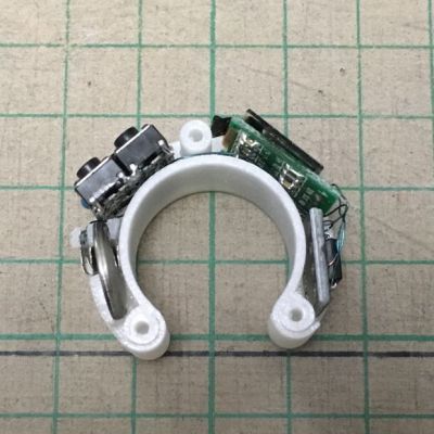
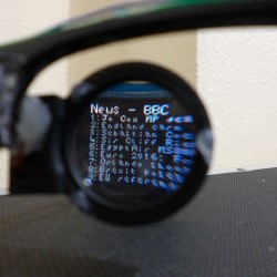 For his project, [Harris Shallcross] used a small 0.95″ diagonal 96×64 color OLED as the display. The lens is from a knockoff Google Cardboard headset, and is held in a 3D printed piece that slides along a wire rail to adjust focus. The display uses a custom font and is driven by an STM32 microcontroller on a small custom PCB, with an HM11 BLE module to receive data wirelessly. Power is provided by a rechargeable lithium-ion battery with a boost converter. An Android app handles sending small packets of data over Bluetooth for display. The prototype software handles display of time and date, calendar, BBC news feed, or weather information.
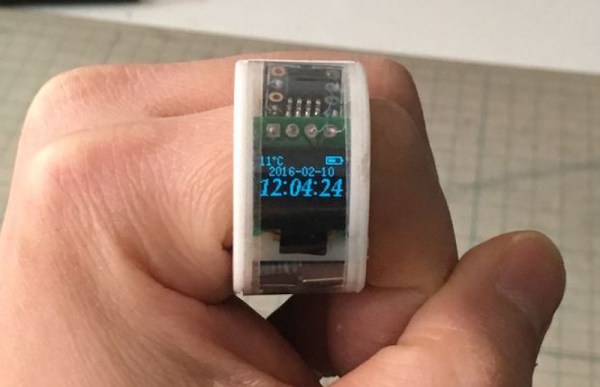
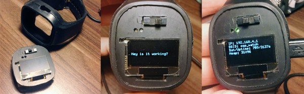
 The current iteration is complete and builds upon