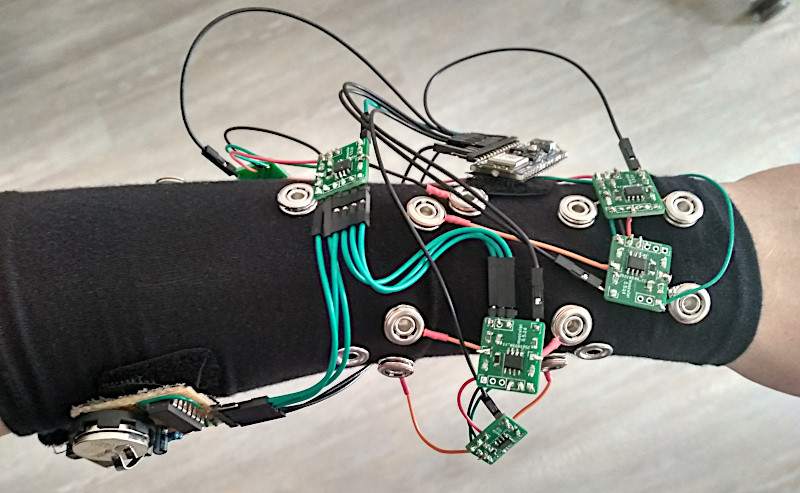
We don’t see many EMG (electromyography) projects, despite how cool the applications can be. This may be because of technical difficulties with seeing the tiny muscular electrical signals amongst the noise, it could be the difficulty of interpreting any signal you do find. Regardless, [hut] has been striving forwards with a stream of prototypes, culminating in the aptly named ‘Prototype 8’
The current prototype uses a main power board hosting an Arduino Nano 33 BLE Sense, as well as a boost converter to pump up the AAA battery to provide 5 volts for the Arduino and a selection of connected EMG amplifier units. The EMG sensor is based around the INA128 instrumentation amplifier, in a pretty straightforward configuration. The EMG samples along with data from the IMU on the Nano 33 BLE Sense, are passed along to a connected PC via Bluetooth, running the PsyLink software stack. This is based on Python, using the BLE-GATT library for BT comms, PynPut handing the PC input devices (to emit keyboard and mouse events) and tensorflow for the machine learning side of things. The idea is to use machine learning from the EMG data to associate with a specific user interface event (such as a keypress) and with a little training, be able to play games on the PC with just hand/arm gestures. IMU data are used to augment this, but in this demo, that’s not totally clear.
An earlier prototype of the PsyLink.
All hardware and software can be found on the project codeberg page, which did make us double-take as to why GnuRadio was being used, but thinking about it, it’s really good for signal processing and visualization. What a good idea!
Obviously there are many other use cases for such a EMG controlled input device, but who doesn’t want to play Mario Kart, you know, for science?
Checkout the demo video (embedded below) and you can see for yourself, just be aware that this is streaming from peertube, so the video might be a little choppy depending on your local peers. Finally, if Mastodon is your cup of tea, here’s the link for that. Earlier projects have attempted to dip into EMG before, like this Bioamp board from Upside Down Labs. Also we dug out an earlier tutorial on the subject by our own [Bil Herd.]
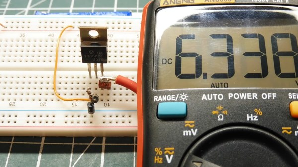
It’s late at night. The solder smoke keeps getting in your tired eyes, but your project is nearly done. The main circuit is powered by your 13.8 V bench supply, but part of the circuit needs 9 V. You dig into your stash to find your last LM7809 voltage regulator, but all you have is a bunch of LM7805’s. Are you done for the night? Not if you’ve watched [0033mer]’s Simple Electronic Circuit Hacks video! You know just what to do. The ground pin of a LM7805 connects to the cathode of a TL431 programmable Zener diode pulled from an old scrapped TV. The diode is referenced to a voltage divider, and voila! Your LM7805 is now putting out a steady 9 V.
How did [0033mer] become adept at doing more with less? As he explains in the video below, his primary source of parts in The Time Before The Internet was old TV’s that were beyond repair. Using N-Channel MOSFETs to switch AC, sensing temperature changes with signal diodes, and even replacing a 555 with a blinking LED are just a few of the hacks covered in the video below the break.
We especially appreciated the simple, to-the-point presentation that inspires us to keep on hacking in the truest sense: Doing more with less! If you enjoy a good diode hack like we do, you will likely appreciate learning Diode Basics by W2AEW, or a Diode Based Radiation Detector.
Thank you [DSM] for the tip! Be sure to submit your the cool things you come across to our Tips Line!
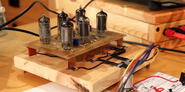
Some of you may remember a recent project that featured on these pages, a 555 timer reproduced using vacuum tubes. Its creator [Usagi Electric] was left at loose ends while waiting for a fresh PCB revision of the 555 to be delivered, so set about creating a new vacuum tube model of a popular chip, this time the ubiquitous 741 op-amp. (Video, embedded below.)
The circuit is fairly straightforward, using six small pentodes. The first two are a long-tailed pair as might be expected, followed by two gain stages, then a final gain stage feeding a cathode follower with feedback. It’s neatly built on a PCB with IC-style “pins” made from more PCB material, then put in a huge replication of an IC socket on a wooden baseboard.
The result is an op-amp, but not necessarily a good one. He looks at the AC performance instead of the DC even though it’s a fully DC-coupled circuit, and finds that while it performs as expected in a classic op-amp circuit it still differs from the ideal at higher gain. The frequency response is poor too, something he rectifies by replacing the feedback capacitor with a smaller value. Sadly he doesn’t look at its common mode performance, though we’d expect that without close matching of the tubes it might leave something to be desired.
It’s obvious that this project would never be selected as an op-amp given the quality of even the cheapest silicon op-amp in comparison. But its value is in a novelty, a talking point, and maybe a chance to learn about op-amps. For that, we like it.
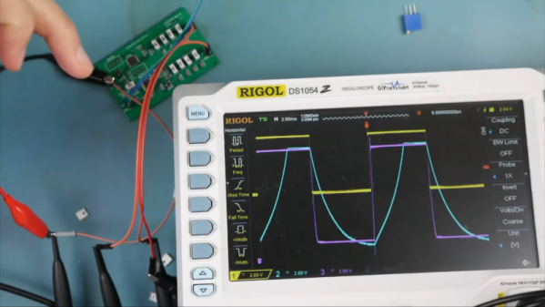
Op amps are generally pretty easy to apply, but there are some practical nonideal behaviors you have to keep in mind. [EEforEveryone] takes a test board with some 2X amplifiers on it and — after some fiddling around with the scope probes — demonstrates the effect of capacitive loading on the output of an op amp. (Video, embedded below.)
The op amp in question is the OP07. In fact, there are two identical opamps looking at the single input. The output of one op amp feeds directly to the scope probes. The second one passes through a bipolar transistor buffer consisting of an NPN and PNP transistor. Both outputs have optional capacitors that can be jumpered in or out of the circuit.
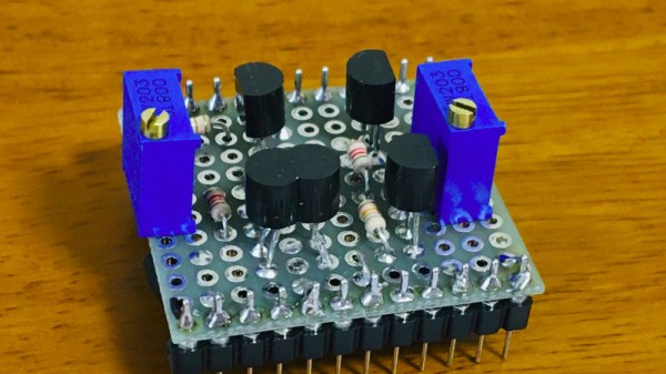
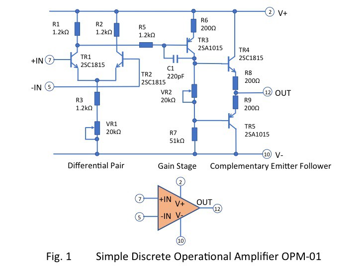
If we had to pick one part to crown as the universal component in the world of analogue electronics, it would have to be the operational amplifier. The humble op-amp can be configured into so many circuit building blocks that it has become an indispensable tool for designers. It’s tempting to treat an op-amp as a triangular black box in a circuit diagram, but understanding its operation gives an insight into analogue electronics that’s worth having. [Mitsuru Yamada]’s homemade op-amp using discrete components is thus a project of interest, implementing as it does a complete simple op-amp with five transistors.
Looking at the circuit diagram it follows the classic op-amp with a long-tailed pair of NPN transistors driving a PNP gain stage and finally a complimentary emitter follower as an output buffer. It incorporates the feedback capacitor that would have been an external component on early op-amp chips, and it has a couple of variable resistors to adjust the bias. Keen eyed readers will notice its flaws such as inevitably mismatched transistors and the lack of a current mirror in the long-tailed pair, but using those to find fault in a circuit built for learning is beside the point. He demonstrated it in use, and even goes as far as to show it running an audio power amplifier driving a small speaker.
In the last Circuit VR we looked at some basic op amp circuits in a simulator, including the non-inverting amplifier. Sometimes you want an amplifier that inverts the signal. That is a 5V input results in a -5V output (or -10V if the amplifier has a gain of 2). This corresponds to a 180 degree phase shift which can be useful in amplifiers, filters, and other circuits. Let’s take a look at an example circuit simulated with falstad.
Remember the Rules
Last time I mentioned two made up rules that are good shortcuts for analyzing op amp circuits:
The inputs of the op amp don’t connect to anything internally.
The output mysteriously will do what it can to make the inputs equal, as far as it is physically possible.
As a corollary to the second rule, you can easily analyze the circuit shown here by thinking of the negative (inverting) terminal as a virtual ground. It isn’t connected to ground, yet in a properly configured op amp circuit it might as well be at ground potential. Why? Because the + terminal is grounded and rule #2 says the op amp will change conditions to make sure the two terminals are the same. Since it can’t influence the + terminal, it will drive the voltage through the resistor network to ensure the – terminal is at 0V.
Circuit simulations are great because you can experiment with circuits and make changes with almost no effort. In Circuit VR, we look at circuits using a simulator to do experiments without having to heat up a soldering iron or turn on a bench supply. This time, we are going to take a bite of a big topic: op amps.
The op amp — short for operational amplifier — is a packaged differential amplifier. The ideal op amp — which we can’t get — has infinite gain and infinite input impedance. While we can’t get that in real life, modern devices are good enough that we can pretend like it is true most of the time.
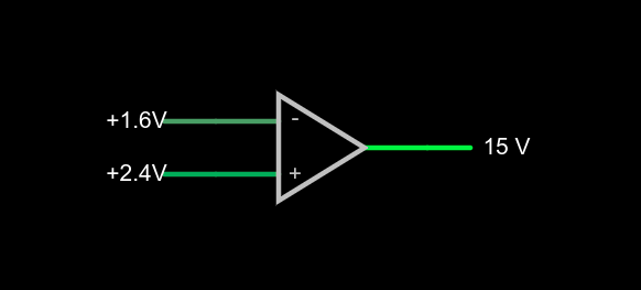
a very simple op amp circuit with some detail omitted
If you open this circuit in the Falstad simulator, you’ll see two sliders to the right where you can tweak the input voltage. If you make the voltages the same, the output will be zero volts. You might think that a difference amplifier would take inputs of 1.6V and 2.4V and either produce 0.8V or -0.8V, but that’s not true. Try it. Depending on which input you set to 2.4V, you’ll get either 15V or -15V on the output. That’s the infinite gain. Any positive or negative output voltage will quickly “hit the rail” or the supply voltage which, in this case, is +/-15V.
Practical Concerns
The biggest omitted detail in the schematic symbol above is that there’s no power supply here, but you can guess that it is +/- 15V. Op amps usually have two supplies, a positive and a negative and while they don’t have to be the same magnitude, they often are. Some op amps are specifically made to work with a single-ended supply so their negative supply can connect to ground. Of course, that presupposes that you don’t need a negative voltage output.
The amount of time it takes the output to switch is the slew rate and you’ll usually find this number on the device datasheet. Obviously, for high-speed applications, a fast slew rate is important, particularly if you want to use the circuit as a comparator as we are here.
Other practical problems arise because the op amp isn’t really perfect. A real op amp would not hit the 15V rail exactly. It will get close depending on how much current you draw from the output. The higher the current, the further away from the rails you get. Op amps will also have some offset that will prevent it from hitting zero when the inputs are equal, although on modern devices that can be very low. Some older devices or those used in high-precision designs will have a terminal to allow you to trim the zero point exactly using an external resistor.
Op Amps Can Provide Steady Voltage Under Variable Load
Rather than dig through a lot of math, you can deal with nearly all op amp circuits if you remember two simple rules:
The inputs of the op amp don’t connect to anything internally.
The output mysteriously will do what it can to make the inputs equal, as far as it is physically possible.
1x amplifier
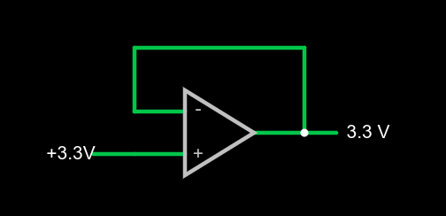
That second rule will make more sense in a minute, but we already see it in action. Set the simulator so the – input (the inverting input) is at 0V and the noninverting input (+) is at 4V. The output should be 15V. The output is trying to make the inverting input match the noninverting one, but it can’t because there is no connection. The output would like to provide an infinite amount of voltage, but it can only go up to the rail which is 15V.
We can exploit this to make a pretty good x1 amplifier by simply shorting the output to the – terminal. Remember, our rules say the input terminals appear to not connect to anything, so it can’t hurt. Now the amplifier will output whatever voltage we put into it:
You might wonder why this would be interesting. Well, we will learn how to increase the gain, but you actually see this circuit often enough because the input impedance is very high (infinite in theory, but not practice). And the output impedance is very low which means you can draw more current without disturbing the output voltage much.
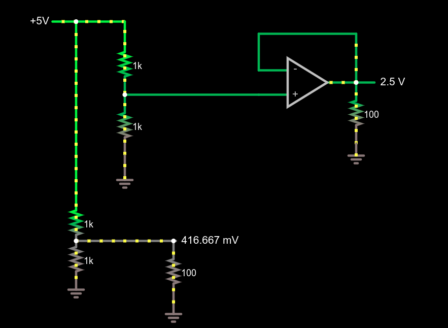
Comparing voltage divider performance with and without a 1x amplifier
This circuit demonstrates the power of a 1x amplifier. Both voltage dividers produce 2.5V with no load. However, with a 100 ohm load at the output, the voltage divider can only provide around 400mV. You’d have to account for the loading in the voltage divider design and if the load was variable, it wouldn’t be possible to pick a single resistor that worked in all cases. However, the top divider feeds the high impedance input of the op amp which then provides a “stiff” 2.5V to whatever load you provide. As an example, try changing the load resistors from 100 ohms to different values. The bottom load voltage will swing wildly, but the top one will stay at 2.5V.
Don’t forget there are practical limits that won’t hold up in real life. For example, you could set the load resistance to 0.1 ohms. The simulator will dutifully show the op amp sourcing 25A of current through the load. Your garden-variety op amp won’t be able to do that, nor are you likely to have the power supply to support it if it did.
What’s Being Amplified?
This is an amplifier even though the voltage stayed the same. You are amplifying current and, thus, power. Disconnect the bottom voltage divider (just delete the long wire) and you’ll see that the 5V supply is providing 12.5 mW of power. The output power is 62.5 mW and, of course, varies with the load resistor.
Notice how this circuit fits the second rule, though. When the input changes, the op amp makes its output equal because that’s what makes the + and – terminals stay at the same voltage.
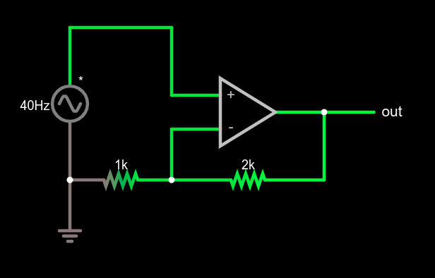
Of course, we usually want a higher voltage when we amplify. We can do that by building a voltage divider in the feedback loop. If we put a 1:2 voltage divider in the loop, the output will have to double to match the input and, as long as that’s physically possible, that’s what it will do. Obviously, if you put in 12V it won’t be able to produce 24V on a 15V supply, so be reasonable.
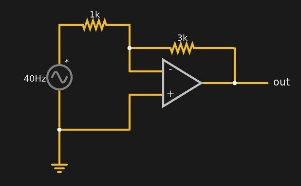
Non-inverting amplifier example
This type of configuration is called a non-inverting amplifier because, unlike an inverting amplifier, an increase in the input voltage causes an increase in the output voltage and a decrease in input causes the output to follow.
Note that the feedback voltage divider isn’t drawn like a divider, but that’s just moving symbols on paper. It is still a voltage divider just like in the earlier example. Can you figure the voltage gain of the stage? The voltage divider ratio is 1:3 and, sure enough, a 5V peak on input turns into a 15V peak on the output, so the gain is 3. Try changing the divider to different ratios.
What’s Next?
While it isn’t mathematically rigorous, thinking of the op amp as a machine that makes its inputs equal is surprisingly effective. It certainly made the analysis of these simple circuits, the comparator, the buffer amplifier, and a general non-inverting amplifier simple.
There are, of course, many other types of amplifiers, as well as other reasons to use op amps such as oscillators, filters, and other even more exotic circuits. We’ll talk about some of them next time and the idea of a virtual ground, which is another helpful analysis rule of thumb.