The 1970s was a great time to be an electronics hobbyist, as a whole new world of analogue integrated circuits was coming down in price while new devices would appear to tempt the would-be constructor. Magazines and project books were full of simple circuits to do all manner of fun things, including many synthesizers and sound generators.
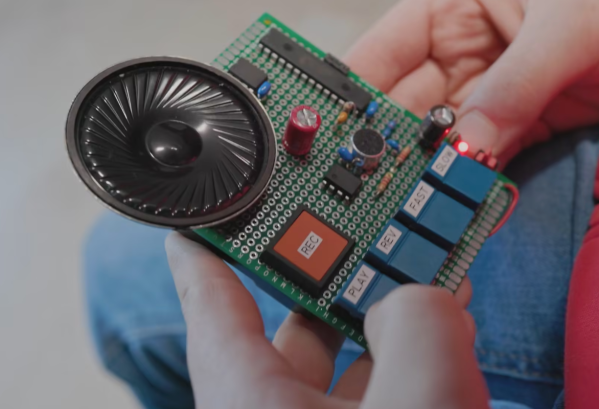
We’re reminded of those days by [Burkhard Kainka]’s triggered sound generator, which couples an op-amp timer to another op-amp phase shift oscillator to produce a sound described as “the unwilling meowing of a cat, which does not want to be disturbed“. Yes, we did make things like this back in the day.
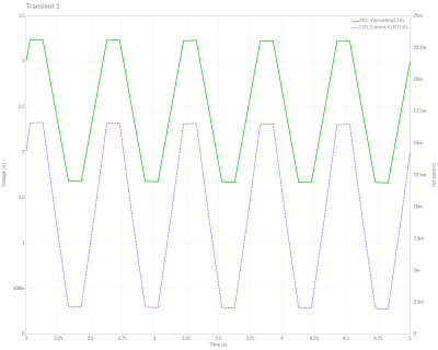
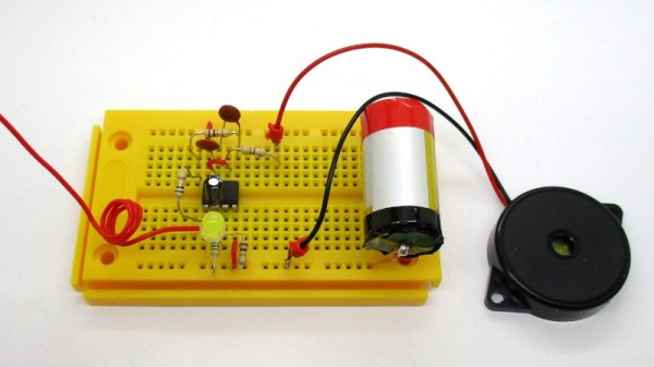
The timer is triggered by a few millivolts on its input, which can come from a bit of mains hum or a flash of light to an LED operating as a photodiode. This provides enough DC voltage to the input of the phase shift oscillator to start oscillation, and in turn the oscillator drives a piezo speaker. It’s a fun little project, it shows that a microcontroller isn’t always needed to make something work, and maybe those of you without the experience of a 1970s childhood can learn a little bit of analogue magic from it. Need to know op-amps better? Read our primer!