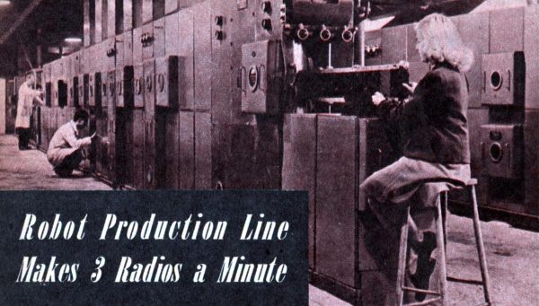
Get Over Your Fears

Some projects are just too complex, that’s for sure. But I’d be willing to bet that some things you think are too difficult actually aren’t, and it may be that all you need to get over your personal hurdle is a good demonstration. Here come three cases in point.

I was looking at the new Raspberry Pi Compute Module last weekend. They have a whole bunch of high-speed traces: things like Gigabit Ethernet, HDMI, and those crazy-fast SDI serial camera interfaces. I have no experience in high-speed design and layout at all, and frankly it gives me the willies. But the Raspberries also shipped me an IO demo board, and concomitant KiCAD design files, with the review board. Looking at it, they were just wires — maybe pairwise length-matched and impedance controlled — but also just wires. Opening up the KiCAD board file and clicking on the traces just like I do with my own designs, I’m a lot less scared. That was a revelation for me.

In a great writeup of his experience building ten different Linux single-board-computers from scratch, Jay Carlson had a similar effect on me. I would never have considered breaking out the hotplate for some CPU-and-DRAM action, and I’ve never had to lay out a PCB with a high density BGA chip before either. I’m not quite into Dunning-Kruger territory yet; I still have a healthy respect for the layout intricacies in fanning out a tight BGA CPU into a DRAM. But Jay’s frank assessments of what is easy and what is hard make it all seem within the realm of the doable.

As Mike and I were talking on the podcast about Jay’s work, Mike came clean about his fear of BGAs. I’ve done enough reflow-plate soldering, with parts that have a lead pitch that’s a factor of two finer than the 0.8 mm pitch BGAs in question, so it doesn’t seem implausible to me. And I’m 100% sure Mike could pull it off too, but he is in need of a BGA guru. Any good hobbyist videos out there?

Being a nerdy type, I’m much more focused on the knowledge and the inspiration, but maybe the courage is equally important — at least I think I undervalue it. I don’t need to lay out HDMI lines, or build a from-scratch Linux box, but I am no longer afraid that I couldn’t, and that’s because I’ve seen detailed examples of fellow hackers who’ve done the same. I might not get it right on the first shot, but I’m not afraid to try, and I wouldn’t have said the same before looking over other folks’ shoulders. Forza e corragio!

Let KiCad And Python Make Your Coils

We like to pretend that our circuits are as perfect as our schematics. But in truth, PCB traces have unwanted resistance, capacitance, and inductance. On the other hand, that means you can use those traces to build components. For example, it isn’t uncommon to see a very small value current sense resistor be nothing more than a long PC board trace. Using PC layers for decoupling capacitance and creating precise transmission lines are other examples. [IndoorGeek] takes us through his process of creating coils on the PCB using KiCad. To help, he used a Python script that works out the circles, something KiCAD has trouble with.

The idea is simple. A coil of wire has inductance even if it is a flat copper trace on a PCB. In this case, the coils are more for the electromagnetic properties, but the same idea applies if you wanted to build tuned circuits. The project took inspiration from FlexAR, an open-source flexible PCB magnet.

Continue reading “Let KiCad And Python Make Your Coils”

Put That New Resin Printer To Work Making PCBs

With all the cool and useful parts you can whip up (relatively) quickly on a 3D printer, it’s a shame you can’t just print a PCB. Sure, ordering a PCB is quick, easy, and cheap, but being able to print one-offs would peg the needle on the instant gratification meter.

[Peter Liwyj] may just have come up with a method to do exactly that. His Instructables post goes into great detail about his method, which uses an Elegoo Mars resin printer and a couple of neat tricks. First, a properly cleaned board is placed copper-side down onto a blob of SLA resin sitting on the print bed. He tricks the printer into thinking the platform is all the way down for the first layer by interrupting the photosensor used to detect home. He lets the printer go through one layer of an STL file that contains his design, which polymerizes a thin layer of plastic onto the copper. The excess resin is wiped gently away and the board goes straight into a ferric chloride etching bath. The video below shows the whole process.

As simple as it sounds, it looks like it works really well. And [Peter] didn’t just stumble onto this method; he approached it systematically and found what works best. His tips incude using electrical tape as a spacer to lift the copper off the print surface slightly, cleaning the board with Scotchbrite rather than sandpaper, and not curing the resin after printing. His toolchain is a bit uncoventional — he used SketchUp to create the traces and exported the STL. But there are ways to convert Gerbers to STLs, so your favorite EDA package can probably fit in to the process too.

Don’t have a resin printer? Don’t worry — FDM printers can work too.

Continue reading “Put That New Resin Printer To Work Making PCBs”

Patience Beats Rage-Quit In Shattered Xbox Controller Repair

There are negative-one hacks to this project. Someone lost at their game, lost their temper, then raged at their Xbox controller with some horsepower. The result is that [Taylor Burley] gets a free controller with a non-responsive joystick out of the deal, and since he had nothing to lose, he decided to heat up the iron and bring the controller back to life.

The majority of the project is told in pictures and through the narration in the video below. In removing the joystick, [Taylor] opts for the technique of doping the connections with fresh solder (we assume containing lead for easier melting) before reaching for the desoldering wick. The diagnosis stage is brief because when the joystick lifts away, the PCB falls apart into two separate pieces! The next step was to glue the two halves together with cyanoacrylate to get into the nooks and crannies, then epoxy to provide structure. Solder bridges were not going to jump that gap, so he used 30ga wire and attached it wherever he could scrape away some solder mask. Best of all, it worked when he reattached the joystick. Job well done.

Xbox controllers are not a scarce commodity, so people do not spend their idle hours fixing them, but not many people can claim experience. Maybe someday the stakes will be higher and he will have the courage to repair vintage electronics. We won’t rant on how things aren’t built to last, and how we don’t train people to fix things. Today, we want to focus on someone who used their time to repair and learn.

Continue reading “Patience Beats Rage-Quit In Shattered Xbox Controller Repair”

DIY Relay Module Saves Time

As any programmer could tell you, there’s significant value in automating a process that is performed often enough. The more times that process is used, the more it makes sense to automate it or at least improve its efficiency. This rule isn’t limited to software though; improvements to hardware design can also see improvements in efficiency as well. For that reason, [Hulk] designed a simple relay module in order to cut the amount of time he spends implementing this solution in his various other projects.

While driving a relay with a transistor is something fundamental, this project isn’t really about that per se. It’s about recognizing something that you do too much, and then designing that drudgery out of your projects. [Hulk] was able to design a PCB with 12 modules on it, presumably saving fabrication costs. He can then easily populate them with specific components as soon as he needs one. Another benefit of designing something like this yourself, rather than an off-the-shelf relay module, is that you can do away with any useless features you’ll never need (or add ones that aren’t available in commercial devices).

We can appreciate the efficiency gains this would make for our next project that needs a simple driver for a light, garage door opener, or any other binary electronic device. It can be a hassle to go find the correct transistor and relay, solder it all on the project board, and hope it all works. A pre-made solution solves all these issues, but we do wish the schematics were available to keep us from having to design our own. Driver boards are a pretty common project for all the different types of relays we see around here, so there is probably one available out there.

Perfect Photographs For PCB Reverse Engineering

There’s an unexpected part of hacking that is very difficult to get right, namely photographing printed circuit boards. Everything seems to catch the light, making for a complex dance of manipulating light sources and camera angles. We were thus captured by [Roman Valls]’ budget rig for taking PCB photos that makes ingenious use of roadside trash to achieve a result.

It was inspired by a video featuring a much more accomplished rig, which he set out to emulate for much less outlay. Instead of an expensive lens, he’s using a Nikon camera with its kit lens. And instead of a tripod there’a a scrap drawer salvaged from the roadside and modified to become a camera holder. Lighting is diffused by baking paper, and the result is a rig that can photograph PCBs with neutral lighting and without annoying highlights.

We especially like work that takes junk and makes something useful from it, and though our purpose isn’t in reverse engineering it’s impressive to see how well the technique reveals the traces. We’ll definitely be experimenting with some of the techniques herein, and those lighting tips might also work with the Hackaday ear camera microscope.

Simultaneous Soldering Station

Soldering irons are a personal tool. Some folks need them on the cool side, and some like it hot. Getting it right takes some practice and experience, but when you find a tip and temp that works, you stick with it. [Riccardo Pittini] landed somewhere in the middle with his open-source soldering station, Soldering RT1. When you start it up, it asks what temperature you want, and it heats up. Easy-peasy. When you are ready to get fancy, you can plug in a second iron, run off a car battery, record preset temperatures, limit your duty-cycle, and open a serial connection.

The controller has an Arduino bootloader on a 32u4 processor, so it looks like a ProMicro to your computer. The system works with the RT series of Weller tips, which have a comprehensive lineup. [Riccardo] also recreated SMD tweezers, and you can find everything at his Tindie store.

Soldering has a way of bringing out opinions from novices to masters. If we could interview our younger selves, we’d have a few nuggets of wisdom for those know-it-alls. If ergonomics are your priority, check out TS100 3D-printed cases, which is an excellent iron, in our opinion.