Fail Of The Week: How Not To Design An RF Signal Generator

We usually reserve the honor of Fail of the Week for one of us – someone laboring at the bench who just couldn’t get it together, or perhaps someone who came perilously close to winning a Darwin Award. We generally don’t highlight commercial products in FotW, but in the case of this substandard RF signal generator, we’ll make an exception.

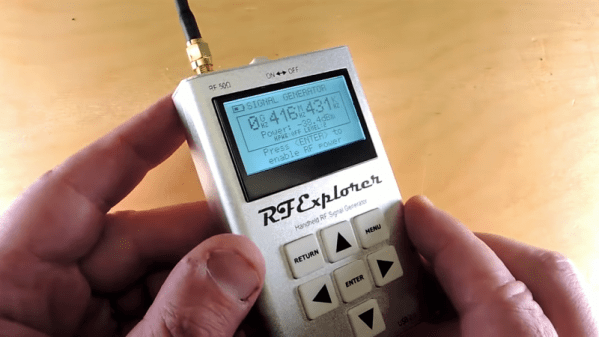
We suppose the fail-badge could be pinned on [electronupdate] for this one in a way; after all, he did shell out $200 for the RF Explorer signal generator, which touts coverage from 24 MHz to 6 GHz. But in true lemons-to-lemonade fashion, the video below he provides us with a thorough analysis of the unit’s performance and a teardown of the unit.

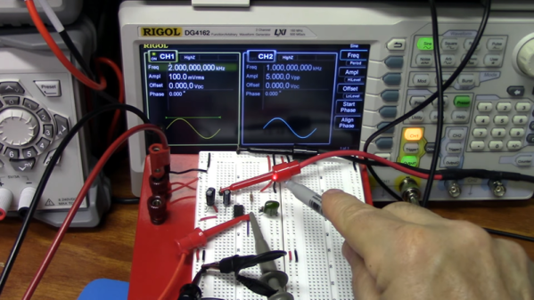
The first step is a look at the signal with a spectrum analyzer, which was not encouraging. Were the unit generating a pure sine wave as it should, we wouldn’t see the forest of spikes indicating harmonics across the band. The oscilloscope isn’t much better; the waveform is closer to a square wave than a sine. Under the hood, he found a PIC microcontroller and a MAX2870 frequency synthesizer, but a conspicuous absence of any RF filtering components, which explains how the output got so crusty. Granted, $200 is not a lot to spend compared to what a lab-grade signal generator with such a wide frequency range would cost. And sure, external filters could help. But for $200, it seems reasonable to expect at least some filtering.

We applaud [electronupdate] for taking one for the team here and providing some valuable tips on RF design dos and don’ts. We’re used to seeing him do teardowns of components, like this peek inside surface-mount inductors, but we like thoughtful reviews like this too.

Continue reading “Fail Of The Week: How Not To Design An RF Signal Generator”

Learn Something About Phase Locked Loops

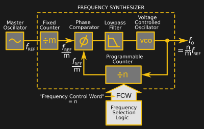
The phase locked loop, or PLL, is a real workhorse of circuit design. It is a classic feedback loop where the phase of an oscillator is locked to the phase of a reference signal using an error signal in the same basic way that perhaps a controller would hold a temperature or flow rate in a physical system. That is, a big error will induce a big change and little errors induce little changes until the output is just right. [The Offset Volt] has a few videos on PLLs that will help you understand their basic operation, how they can multiply frequencies (paradoxically, by dividing), and even demodulate FM radio signals. You can see the videos below.

The clever part of a PLL can be found in how it looks at the phase of two signals. For signals to be totally in phase, they must be at the same frequency and also must ebb and peak at the same point. It should be clear that if the frequency isn’t the same the ebbs and peaks can’t line up for any length of time. By detecting how much the signals don’t line up, an error voltage can be generated. That error voltage is used to adjust the output oscillator so that it matches the reference oscillator.

Of course, it wouldn’t be very interesting if the output frequency had to be the same as the reference frequency. The clever trick comes by dividing the output frequency. For example, a 100 MHz crystal oscillator is difficult to design. But taking a voltage-controlled oscillator at 100 MHz (nominal) and dividing its output by 100 will give you a signal you can lock to a 1 MHz crystal oscillator which is, of course, trivial to build.

Continue reading “Learn Something About Phase Locked Loops”

In-Band Signaling: Coded Squelch Systems

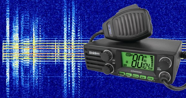
In the first part of our series on in-band signaling, we discussed one of the most common and easily recognizable forms of audio control, familiar to anyone who has dialed a phone in the last fifty years – dual-tone multifrequency (DTMF) dialing. Our second installment will look at an in-band signaling method that far fewer people have heard, precisely because it was designed to be sub-audible — coded squelch systems for public service and other radio services. Continue reading “In-Band Signaling: Coded Squelch Systems”

A Great Guide To Software PLLs

There are some things that you think you know quite well because you learned them in your youth and you understand their principles of operation. Then along comes a link in your morning feed that reminds you of the limits of your knowledge, and you realize that there is a whole new level of understanding to be reached.

Take Phase Locked Loops (PLLs) for example. You learn how they work, you use them for frequency synthesis, and you know they can do other things like recover noisy clock lines and do FM demodulation. But then you read [Paul Lutus’] Understanding Phase-Locked Loops page, and a whole new vista opens.

He’s discussing PLLs in the context of software, as part of a weather fax decoder project, and this allows a perspective that was unavailable to those of us who learned about them through the medium of hardware such as the venerable 4046 CMOS chip. We can easily look at different PLLs with varying parameters, for example their use with a narrowband loop filter to retrieve signals buried in the noise, all through some straightforward code tweaks rather than extensive circuitry. It’s a page that’s a few years old now, but resources like this one do not age.

If PLLs are entirely new to you then you need to reat last year’s excellent PLL primer by Hackaday’s own [Al Williams].

[via Hacker News]

[PLL diagram: Chetvorno CC0]

In-Band Signaling: Dual-Tone Multifrequency Dialing

One late night many decades ago, I chanced upon a technical description of the Touch-Tone system. The book I was reading had an explanation of how each key on a telephone sends a combination of two tones down the wire, and what’s more, it listed the seven audio frequencies needed for the standard 12-key dial pad. I gazed over at my Commodore 64, and inspiration hit — if I can use two of the C64’s three audio channels to generate the dual tones, I bet I can dial the phone! I sprang out of bed and started pecking out a Basic program, and in the wee hours I finally had it generating the recognizable Touch-Tones of my girlfriend’s phone number. I held the mouthpiece of my phone handset up to the speaker of my monitor, started the program, and put the receiver to my ear to hear her phone ringing! Her parents were none too impressed with my accomplishment since it came at 4:00 AM, but I was pretty jazzed about it.

Since that fateful night I’ve always wondered about how the Touch-Tone system worked, and in delving into the topic I discovered that it’s part of a much broader field of control technology called in-band signaling, or the use of audible or sub-audible signals to control an audio or video transmission. It’s pretty interesting stuff, even when it’s not used to inadvertently prank call someone in the middle of the night. Continue reading “In-Band Signaling: Dual-Tone Multifrequency Dialing”

STM32 Analog Converter Phase Noise

[Avian] has been using STM32 ARM processors to sample RF for a variety of applications. At first, he was receiving relatively wide TV signals. Recently, though, he’s started dealing with very narrow signals and he found that his samples had a lot of spread in the frequency domain that he didn’t expect.

What followed was some detective work that resulted in a determination that phase noise was the culprit. But why? [Avian] took some measurements and noticed that the phase noise almost exactly matched the phase noise specification for the STM32’s phase locked loop (PLL).

Unfortunately, there didn’t seem to be a good way to avoid using the PLL without major changes to the rest of the circuit. However, it was quite the learning experience and something to be aware of when counting on built-in converters for high-accuracy measurements.

One of the best things about this post is the references to more information. There’s a great explanation of phase noise, as well as a specific application note about clock jitter and analog converters.

We’ve talked about phase noise in direct digital synthesis a few times. But usually, it is pretty obvious like when you are asking a CPU to double as an RF transmitter. [Avian’s] post was a bit more of a detective story.

Unlock The Phase Locked Loop

If you want a stable oscillator, you usually think of using a crystal. The piezoelectric qualities of quartz means that it can be cut in a particular way that it will oscillate at a very precise frequency. If you present a constant load and keep the temperature stable, a crystal oscillator will maintain its frequency better than most other options.

There are downsides to crystals, though. As you might expect, because crystals are so stable it’s hard to change the frequency much when you want a different one. You can use a trimming capacitor to pull the frequency a little, but to really change frequency, you have to change crystals.

There are other kinds of oscillators that are more frequency agile. However, they aren’t usually as stable. To combine flexibility with crystal-like stability, you can use a Phase Locked Loop (PLL). Many modern systems use direct digital synthesis, but the PLL is a venerable and time-tested technique.

Continue reading “Unlock The Phase Locked Loop”