How Ten Turn Pots Are Made

It is easy to think of a potentiometer as a simple device, but there are many nuances. For example, some pots are linear — a change of a few degrees at the low end will change the resistance the same amount as the same few degrees at the high end. Others are logarithmic. Changes at one end of the scale are more dramatic than at the other end of the scale. But for very precise use, you often turn to the infamous ten-turn pot. Here, one rotation of the knob is only a tenth of the entire range. [Thomas] shows us what’s inside a typical one in the video below.

When you need a precise measurement, such as in a bridge instrument, these pots are indispensable. [Thomas] had a broken one and took that opportunity to peer inside. The resistor part is a coil of wire wound around the inside of the round body. Unsurprisingly, there are ten turns of wire that make up the coil.

The business end, of course, is in the rotating part attached to the knob. A small shuttle moves up and down the shaft, making contact with the resistance wire and a contact for the wiper. The solution is completely mechanical and dead simple.

As [Thomas] notes, these are usually expensive, but you can  — of course — build your own. These are nice for doing fine adjustments with precision power supplies, too.

Continue reading “How Ten Turn Pots Are Made”

A DIY handheld PONG game

DIY Pocket PONG Breaks The Mobile Spell

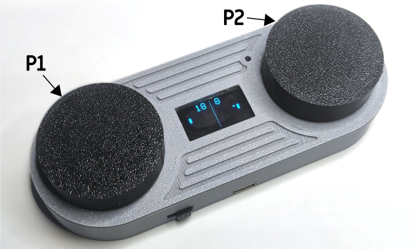
[Minikk], aka [Athul] is about to enter 10th grade and reports that they and their contemporaries are eschewing boring mobile games for 90s stuff and old games like PONG. Well, we already knew the 90s were back, but it’s nice to see that even older stuff is coming along with it. The kids are alright.

Whether you want to play alone or with a friend, it’s a classic to have in your pocket for sure. The brains behind this 70s-era operation is a Seeed Xiao ESP32-C3, which takes input from the two potentiometers and outputs the game on a 128 x 64 OLED. There’s also a small buzzer for when the ball hits the paddle, or you or your friend slips one past the goalie.

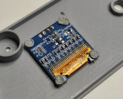
Our favorite part of this build has to be the DIY rivets that hold the OLED in place. [Athul] built posts into the enclosure that get heat-smashed into place with a soldering iron. Pretty neat, huh?

PONG is a specific thrill, certainly. How can it be more thrilling? Maybe with LEDs instead of a screen? Just a thought.

A Classroom-Ready Potentiometer From Pencil And 3D Prints

If you need a potentiometer for a project, chances are pretty good that you’re not going to pick up a pencil and draw one. Then again, if you’re teaching someone how a variable resistor works, that old #2 might be just the thing.

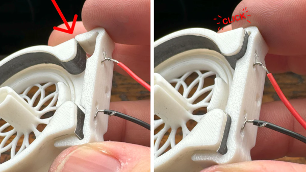
When [HackMakeMod] realized that the graphite in pencil lead is essentially the same thing as the carbon composition material inside most common pots, the idea for a DIY teaching potentiometer was born. The trick was to build something to securely hold the strip while making contact with the ends, as well as providing a way to wipe a third contact across its length. The magic of 3D printing provided the parts for the pot, with a body that holds a thin strip of pencil-smeared paper securely around its inner diameter. A shaft carries the wiper, which is just a small length of stripped hookup wire making contact with the paper strip. A clip holds everything firmly in place. The video below shows the build process and the results of testing, which were actually pretty good.

Of course, the construction used here isn’t meant for anything but demonstration purposes, but in that role, it performs really well. It’s good that [HackMakeMod] left the body open to inspection, so students can see how the position of the wiper correlates to resistance. It also makes it easy to slip new resistance materials in and out, perhaps using different lead grades to get different values.

Hats off to a clever build that should be sure to help STEM teachers engage their students. Next up on the lesson plan: a homebrew variable capacitor.

Continue reading “A Classroom-Ready Potentiometer From Pencil And 3D Prints”

Pimp My Pot Redux, Now Cheaper And Even Better

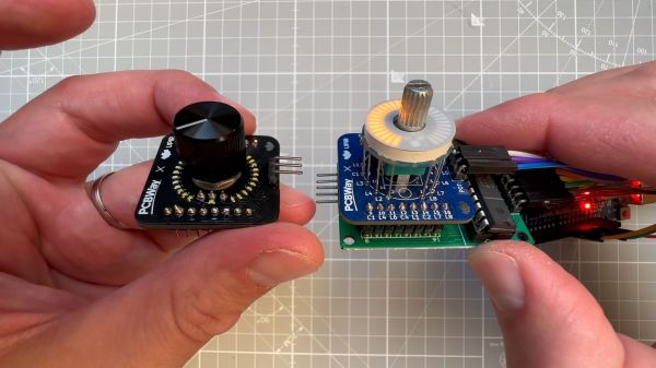
If there’s one thing we like around here more than seeing an improved version of a project we’ve already covered, it’s when the improvements make the original project cheaper. In the case of this LED ring light for pots and encoders, not only is it cheaper than its predecessors, it’s better looking and easier to integrate into your projects.

Right from its start, [upir]’s “Pimp My Pot” project has been all about bringing some zazzle to rotary controls. Knobs with a pointer and a scale on the panel are okay — especially when they go to eleven — but more lights mean more fun. The fun comes at a price, though; the previous version of “PMP” used an off-the-shelf LED ring light with a unit cost of about $10. Not the end of the world, perhaps, but prohibitive, and besides, where’s the fun in just buying a component specifically made for rotary control indication?

The new version shown in the video below is pin-compatible with the driver board [upir] used for the previous version, which is based on the MAX7219 display driver. Modifying the previous board to accommodate 32 white 0402 LEDs over a 270° arc was no mean feat. [upir] covers both creating the schematic and the PCB layout in some detail, providing his usual trove of tool-chain tips for minimizing the amount of manual work needed.

Wisely, [upir] chose to get his boards assembled by the vendor; getting all those LEDs to line up perfectly is a job best left to the robots. While the board is designed for use with pots that mount on either side, we much prefer mounting the pot’s shaft through the board, as it keeps the LEDs closer to the knob. The final price per board works out to about $6.30 in quantities of ten and falls to a trivial $1.70 each for lots of 1,000. Pretty sweet savings on a pretty sweet-looking build.

This is a cool use of a ring of LEDs, but if you prefer the finger kind, you can make that, too. You can do it the easy way or the hard way.

Continue reading “Pimp My Pot Redux, Now Cheaper And Even Better”

High-Resolution MIDI Controller

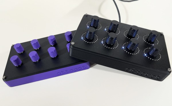
For an older standard, MIDI has remarkable staying power in the music industry. It remains the de facto digital interface between computers and instruments thanks to its open nature, but its age does show a little bit. Sending control change (CC) messages, for example, was originally designed to fit within seven bits, which doesn’t give particularly fine resolution compared to more capable modern computers. To work around that, a fourteen-bit message is possible, doubling the resolution, and this MIDI interface uses this larger amount of data to send these high-resolution CC messages.

The 14-bit messages are actually fairly well documented but are a bit obscure, with very limited hardware support. To that end, [Gero] set about building this control interface to solve that problem. It’s made up of only eight knobs, each of which is mapped one-to-one to a parameter on the computer, allowing the interface to feel more like an analog device where the knob corresponds directly to a change in an aspect of the sound. The platform is built around a Teensy 4.0 and some multiplexers to handle all of the knobs, with the open source software available for anyone to use to modify their actions. [Gero] was aiming for high fidelity for all aspects of this controller, not just the improved digital resolution, and made a number of other improvements to it as well like re-greasing the potentiometer knobs and a custom 3D printed enclosure.

All of the software is available for use, as well as the files to print the case. [Gero] is also working on a PCB to make the construction of the device a little more streamlined, but for now, it requires a bit of soldering off-the-shelf parts together. The MIDI standard is open as well, which allows for a lot of innovation in the creation of musical instruments from unique hardware. This project builds a MIDI synthesizer with parts from a Sega Genesis.

Making A Guitar Go To Eleven, The Hard Way

At the end of the day, all it takes to make a guitar go to eleven is a new knob. Making the knob is another thing — that takes a shop full of machine tools, the expertise to use them, and a whole bunch of time. Then again, if you’re pressed for time, it looks like a 3D printer will do nicely too.

While the 3D printing route is clearly the easier option, it sure seems as if [Chronova Engineering] is more about the journey than the destination. In need of some knob bling for an electric guitar, he takes us through the lengthy process (nicely summarized in the video below) of crafting one from a bar of solid brass. Like all good machining projects, this one starts with making the tools necessary to start the actual build; in this case, it’s a tool to cut the splines needing to mate with the splines on the guitar’s potentiometer shaft. That side quest alone represents probably a third of the total effort on this project, and results in a tool that’s used for all of about 30 seconds.

Aside from spline cutting, there are a ton of interesting machining tidbits on display here. We particularly liked the use of a shaping technique to form the knurling on the knob, as opposed to a standard rotary method, which would have been difficult given the taper on the knob body. Also worth noting are the grinding step that puts a visually interesting pattern on the knob’s top surface, as well as the pantograph used to etch the knob’s markings.

Congrats to [Chronova Engineering] for a great-looking build, and the deep dive into the machinist’s ways. If you’re still interested in custom brass knobs but don’t have a machine shop, we can help with that.

Continue reading “Making A Guitar Go To Eleven, The Hard Way”

Hall Sensors Offer Drop-In Replacement For Drifting Game Console Joysticks

No bananas were harmed in the making of this Hall effect drift-proof joystick replacement. OK, not really — two bananas were turned to mush. But it’s OK, they’re just bananas, after all.

Why bananas, you ask? Because [Marius Heier] uses them to demonstrate what we all intuitively know — that rubbing something over and over again tends to wear it away — but engineers seem to have forgotten. Wear such as this, with resistance material rather than fruits, is what causes the dreaded drift, a problem that the world collectively spends $20 billion a year dealing with, according to [Marius].

While numbers like that seem to be firmly in class-action lawsuit territory, sometimes it’s best to take matters into your own hands and not wait for the courts. The fix [Marius] shows here is to yank the potentiometers off a PS4 joystick and replace them with contactless Hall effect sensors. The end of the shaft for each axis gets a diametral neodymium magnet attached to it, while a 3D printed bracket holds a tiny custom PCB in close proximity. The PCB has an AS5600 Hall sensor, which translates the shaft angle to an analog voltage output. After programming the chip over its I2C bus, the sensor outputs a voltage proportional to the angle of each shaft, just like the original pots, but without all the wear and tear.

While [Marius] is selling these as drop-in replacements for PS4 controllers, he plans to release all the design files so you can build one yourself. He also has his sights set on replacements for PS5 and Xbox controllers, so watch for those. This isn’t his first foray into joystick hacking, having shared his 3D Hall effect and haptic feedback joysticks with us previously.

Continue reading “Hall Sensors Offer Drop-In Replacement For Drifting Game Console Joysticks”