DIY Variacs Get ESP8266 Upgrades

If you’be been hacking and making long enough, you’ve probably run into a situation where you realize that a previous project could be improved with the addition of technology that simply wasn’t available when you built it. Sometimes it means starting over from scratch, but occasionally you luck out and can shoehorn in some new gear without having to go back to the drawing board.

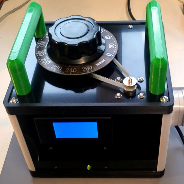
The two isolated variacs that [nop head] built were already impressive, but with the addition of the ESP8266 he was able to add some very slick additional features which really took them to the next level. He’s done an exceptional job detailing the new modifications, including providing all the source for anyone who might be walking down a similar path.

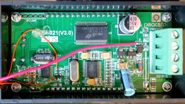
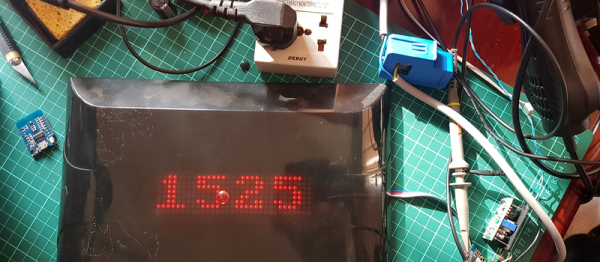
His variacs have digital energy meters right in the front panel which give voltage, amps, and a real-time calculation of watts. After reading an article by [Thomas Scherrer] about sniffing the SPI data out of one of these meters with an Arduino, [nop head] reasoned he could do the same thing with an ESP8266. The advantage being that he could then pull that data out over the network to graph or analyze however he wishes.

For his older variac, he decided to automate the device by adding a stepper and belt to turn the knob. The stepper is controlled by a Pololu stepper driver, which in turn get’s its marching orders from another ESP8266. He even came up with a simple web interface which allows you to monitor and control the variac from your smart device.

We don’t often see many variacs around these parts, and even fewer attempts at building custom ones. It’s one of those pieces of equipment you either can’t live without, or have never even heard of.

Smart Outlet Cover Offers Lessons On Going From Project To Product

Going from idea to one-off widget is one thing; engineering the widget into a marketable product is quite another. So sometimes it’s instructive to take an in-depth look at a project that was designed from the get-go to be a consumer product, like this power indicating wall outlet cover plate. The fact that it’s a pretty cool project helps too.

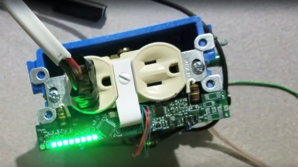
Although [Vitaliy] has been working on this project for a while, he only recently tipped us off to it, and we’re glad he did because there’s a lot to learn here. His goal was to build a replacement cover for a standard North American power outlet that indicates how much power is being used by whatever is plugged into it. He set constraints that included having everything fit into the familiar outlet cover form factor, as well as to not require any modification to the existing outlet or rewiring, so that a consumer can just remove the old cover and put on the new one. Given the extremely limited space inside an outlet cover, these were significant challenges, but [Vitaliy] found a way. Current is sensed with two inductors positioned to sense magnetic flux within the outlet, amplified by a differential amp, and power use is calculated by an ATmega328 for display on 10 LEDs. Power for the electronics is tapped right from the outlet wiring terminals by spring clips, and everything fits neatly inside the cover.

It’s a great design, but not without issues. We look forward to seeing [Vitaliy] tackle those problems and bring this to market. For more on what it takes to turn a project into a product, check out our own [Lewin Day]’s story of bringing a guitar effects pedal to market.

Continue reading “Smart Outlet Cover Offers Lessons On Going From Project To Product”

Read Home Power Meters With RTL-SDR

[k-roy] hates electricity. Especially the kind that can be lethal if you’re not careful. Annoyed by the constant advertisements for the popular Sense Home Energy monitors (which must be installed in the main breaker box by an electrician), [k-roy] set out to find a cheaper and easier way. He wondered how the power company monitored his meter, and guessed correctly that it must be transmitting the information wirelessly. Maybe he could just listen in?

Using a cheap RTL-SDR, it didn’t take long for [k-roy] to tap into this transmission and stumbled across the power readings for his entire neighborhood using a simple command:

~/gocode/bin/rtlamr -msgtype=idm --format=json -msgtype=scm+

Ironically, the hardest part wasn’t snooping on everyone’s power and water usage patterns in the neighborhood, it was trying to figure out which meter was his. In the end, he was able to make some nice graphical layouts of the data with PHP.

We’ve seen some righteous power meter hacks in our time, but this one stands out for its simplicity and elegance. Be sure to check out [k-roy’s] blog for more details, and [rtlamr’s] github for the program used to read the meters.

Thanks to [Jasper J] for the tip!

Instrument Packed Pedal Keeps Track Of Cyclist’s Power

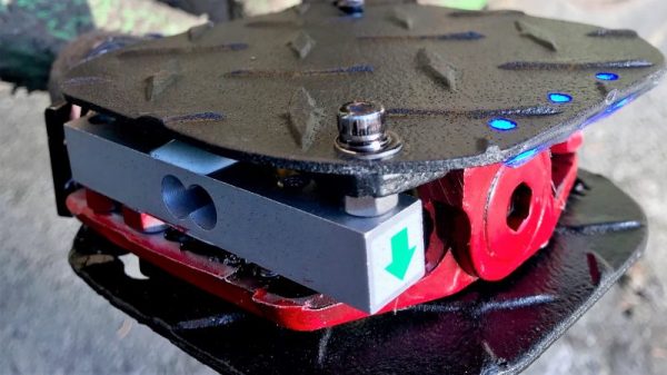
Exactly how much work is required to pedal a bike? There are plenty of ways to measure the power generated by a cyclist, but a lot of them such as heavily instrumented bottom brackets and crank arms, can be far too expensive for casual use. But for $30 in parts you can build this power-measuring bike pedal. and find out just how hard you’re stoking.

Of course it’s not just the parts but knowing what to do with them, and [rabbitcreek] has put a lot of thought and engineering into this power pedal. The main business of measuring the force applied to the crank falls to a pair of micro load cells connected in parallel. A Wemos, an HX711 load-cell amp, a small LiPo pack and charging module, a Qi wireless charger, a Hall sensor, a ruggedized power switch, and some Neopixels round out the BOM. Everything is carefully stuffed into very little space in a modified mountain bike pedal and potted in epoxy for all-weather use. The Hall sensor keeps tracks of the RPMs while the strain gauges measure the force applied to the pedal, and the numbers from a ride can be downloaded later.

We recall a similar effort using a crank studded with strain gauges. But this one is impressive because everything fits in a tidy package. And the diamond plate is a nice touch.

How Many Watts Are You Using?

One of the best smart home hacks is implementing an energy monitor of some kind. It’s easy enough to say that you’re trying to save energy, but without the cold hard data, it’s just talk. Plus, it’s easy and a great way to build up something DIY that the whole family can use.

[Bogdan] built up a simple whole-apartment power monitor from scratch over the weekend, and he’s been nice enough to walk us through the whole procedure, starting with picking up a split-core CT sensor and ending up with a finished project.

The brains of his project are an ESP8266 module, which means that he needed to adapt the CT sensor to put out a voltage that lies within the chip’s ADC range of 0 V to 3.3 V. If you’re undertaking an energy monitor project, it’s as easy as picking the right burden resistor value and then shifting the ground-centered voltage up by 1.6 V or so. We say it’s easy, but it’s nice to have a worked example and some scope shots. The microcontroller reads the ADC frequently, does a little math, and you’re done. Continue reading “How Many Watts Are You Using?”

Hackaday Prize Entry: Smart USB Hub And IoT Power Meter

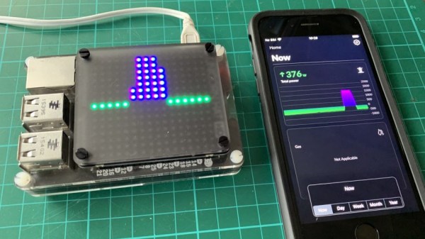
[Aleksejs Mirnijs] needed a tool to accurately measure the power consumption of his Raspberry Pi and Arduino projects, which is an important parameter for dimensioning adequate power supplies and battery packs. Since most SBC projects require a USB hub anyway, he designed a smart, WiFi-enabled 4-port USB hub that is also a power meter – his entry for this year’s Hackaday Prize.

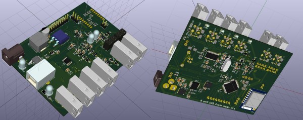
[Aleksejs’s] design is based on the FE1.1s 4-port USB 2.0 hub controller, with two additional ports for charging. Each port features an LT6106 current sensor and a power MOSFET to individually switch devices on and off as required. An Atmega32L monitors the bus voltage and current draw, switches the ports and talks to an ESP8266 module for WiFi connectivity. The supercharged hub also features a display, which lets you read the measured current and power consumption at a glance.

Unlike most cheap hubs out there, [Aleksejs’s] hub has a properly designed power path. If an external power supply is present, an onboard buck converter actively regulates the bus voltage while a power path controller safely disconnects the host’s power line. Although the first prototype is are already up and running, this project is still under heavy development. We’re curious to see the announced updates, which include a 2.2″ touchscreen and a 3D-printable enclosure.

Energy Monitor Optically Couples To Smart Meter

Hackers love to monitor things. Whether it’s the outside temperature or the energy used to take a shower, building a sensor and displaying a real-time graph of the data is hacker heaven. But the most interesting graphs comes from monitoring overall power use, and that’s where this optically coupled smart-meter monitor comes in.

[Michel]’s meter reader is pretty straightforward. His smart wattmeter is equipped with an IR LED that pips for every watt-hour consumed, so optical coupling was a natural approach. The pulse itself is only 10 ms wide, so he built a pulse stretcher to condition the pulse for a PIC microcontroller. The PIC also reads the outside temperature with a DS18B20 and feeds everything to the central power monitor, with an LCD display and a classic Simpson meter to display current power usage. The central monitor sends the power and temperature data to Thingspeak, along with data from [Michel]’s wood-stove monitor and a yet-to-be-implemented water heater monitor.

[Michel] is building out an impressive suite of energy and environmental monitors for his Quebec base of operations. We’re looking forward to seeing how he monitors that water heater, and to see what other ideas he comes up with.

Continue reading “Energy Monitor Optically Couples To Smart Meter”