Single-Stepping The 6502 Processor

Although marketing folk and laypeople may credit [Steve Jobs] as the man behind the success of Apple, those in the tech world know the real truth that without [Steve Wozniak] nothing would have ever gotten off the ground during the early days of the computer company. As an exhibit of his deep knowledge of the machines he was building, take a look at this recreation of a circuit by [Anders] which allows the 6502 processor to step through instructions one at a time, originally designed by [Woz] himself, even though there are still myths floating around the Internet that this type of circuit can’t work.

Like a lot of Internet myths, though, there’s a kernel of truth at the middle. The original 6502 from the mid-70s had dynamic registers, meaning they would lose their values if the chip was run below a critical clock speed. Since single-stepping the processor is much lower than this speed, it seems logical that this might corrupt the data in the registers. But if the clock is maintained to the registers the processor can be halted after each instruction, allowing even the original 6502 to go through its instructions one at a time.

[Anders]’s project sets up this circuit originally laid out by [Steve Wozniak] but updates it a bit for the modern times. Since the technology of the era would have been TTL, modern CMOS logic requires pull-up resistors to keep any inputs from floating. The key design of the original circuit is a set of flip-flops which latch the information on the data bus, and a switch that can be pressed to let the processor grab its next instruction, as well as a set of LEDs that allow the user to see the value on the data bus directly.

Of course, a computer processor of this era would be at a major handicap without a way to debug code that it was running, so there are even dedicated pins that allow this functionality to occur. Perhaps the Internet myth is a bit overblown for that reason alone, but [Anders] is no stranger to the 6502 and has developed many other projects that demonstrate his mastery of the platform.

Continue reading “Single-Stepping The 6502 Processor”

A Mainframe Computer For The Modern Age

The era of mainframe computers and directly programming machines with switches is long past, but plenty of us look back on that era with a certain nostalgia. Getting that close to the hardware and knowing precisely what’s going on is becoming a little bit of a lost art. That’s why [Phil] took it upon himself to build this homage to the mainframe computer of the 70s, which all but disappeared when PCs and microcontrollers took over the scene decades ago.

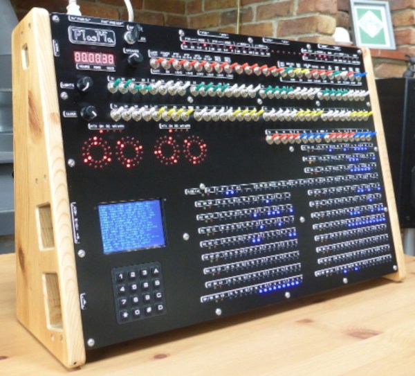
The machine, known as PlasMa, is not a recreation of any specific computer but instead looks to recreate the feel of computers of this era in a more manageable size. [Phil] built the entire machine from scratch, and it can be programmed directly using toggle switches to input values into registers and memory. Programs can be run or single-stepped, and breakpoints can be set for debugging. The internal workings of the machine, including the program counter, instruction register, accumulator, and work registers, are visible in binary lights. Front panel switches let you control those same items.

The computer also hosts three different microcodes, each providing a unique instruction set. Two are based on computers from Princeton, Toy-A, and Toy-B, used as teaching tools. The third is a more advanced instruction set that allows using things like emulated peripherals, including storage devices. If you want to build one or just follow along as the machine is constructed, programmed, and used, [Phil] has a series of videos demonstrating its functionality, and he’s made everything open-source for those more curious. It’s a great way to get a grasp on the fundamentals of computing, and the only way we could think of to get even more into the inner workings of a machine like this is to build something like a relay computer.

Continue reading “A Mainframe Computer For The Modern Age”

Virtual Eurorack Based CPU Computes To The Beat Of A Different Drum Module

In Arthur C. Clarke’s 1972 story “Dial F for Frankenstein”, the worlds first global network of phone exchanges was created by satellite link, and events happened that caused the characters in the story to wonder if the interconnected mesh of machinery had somehow become sentient. And that’s what we wondered when we saw this latest virtual CPU construction built by GitHub user [katef] and made from a virtual analog synthesizer software called VCV Rack.

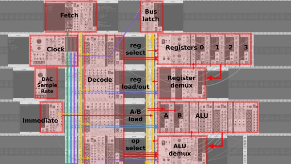
Analogous to a Redstone computer in Minecraft, there’s no physical hardware involved. But instead of making crazy synth sounds for a music project, [katef] has built a functioning CPU complete with an Arithmetic Logic Unit, an adder, and other various things you’ll find in a real CPU such as registers and a clock.

While no mention is made of whether the construct is sentient, [katef] fully documented the build on their GitHub page, and so go check that out for animated pictures, links to more information, and more. It’s quite impressive, if not just a little bonkers. But most good hacks are, right?

We love unique CPU builds, and you might get a kick out of this one made from- that’s right- 555 timers. Thanks to [Myself] on the Hackaday Discord server for the tip, and be sure to send in your favorite outrageous projects to the Hackaday tip line!

Little Hex Tricks Make Little Displays A Little Easier

Depending on the device in hand and one’s temperament, bringing up a new part can be a frolic through the verdant fields of discovery or an endless slog through the grey marshes of defeat. One of the reasons we find ourselves sticking with tried and true parts we know well is that interminable process of configuration. Once a new display controller is mostly working, writing convenience functions to make it easier to use can be very satisfying, but the very first thing is figuring out how to make it do anything at all. Friend of Hackaday [Dan Hienzsch] put together a post describing how to use a particular LED controller which serves as a nice walkthrough of figuring out the right bitmath to make things work, and includes a neat trick or two.

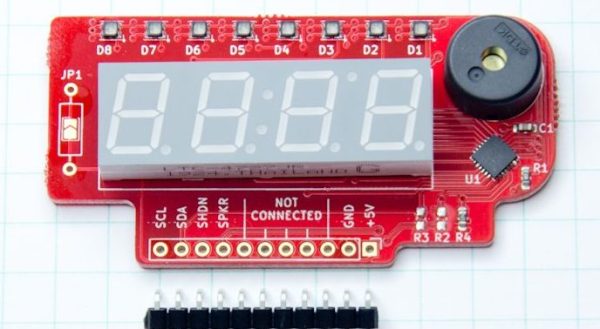
The bulk of the post is dedicated to describing the way [Dan] went about putting together his libraries for a 7-segment display demo board he makes. At its heart the board uses the IS31FL3728 matrix driver from ISSI. We love these ISSI LED controllers because they give you many channels of control for relatively low cost, but even with their relative simplicity you still need to do some bit twiddling to light the diodes you need. [Dan]’s post talks about some strategies for making this easier like preconfigured lookup tables with convenient offsets and masking bits to control RGB LEDs.

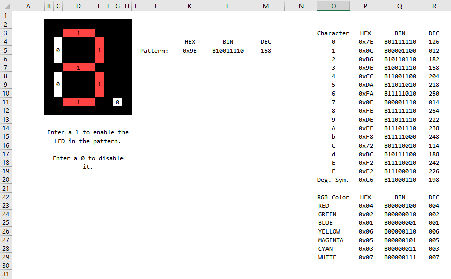
There’s one more trick which we think is the hidden star of the show; a spreadsheet which calculates register values based on “GUI” input! Computing the bit math required to control a display can be an exercise in frustration, especially if the logical display doesn’t fit conveniently in the physical register map of the controller. A spreadsheet like this may not be particularly sexy but it gets the job done; exactly the kind of hack we’re huge fans of here. We’ve mirrored the spreadsheet so you can peek at the formulas inside, and the original Excel document is available on his blog.

These Bit Twiddling Tricks Will Make Your Coworkers Hate You

In the embedded world, twiddling a few bits is expected behavior. Firmware is far enough down the stack that the author may care about the number of bits and bytes used, or needs to work with registers directly to make the machine dance. Usually these operations are confined to the typical shifting and masking but sometimes a problem calls for more exotic solutions. If you need to descend down these dark depths you invariably come across the classic Bit Twiddling Hacks collected by [Sean Eron Anderson]. Here be dragons.

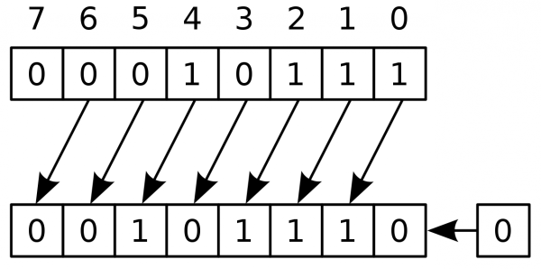
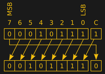
Discussions of bit math are great opportunities to revisit Wikipedia’s superb illustrations

Bit Twiddling Hacks is exactly as described; a page full of snippets and suggestions for how to perform all manner of bit math in convenient or efficient ways. To our surprise upon reading the disclaimer at the top of the page, [Sean] observes that so many people have used the contents of the page that it’s effectively all been thoroughly tested. Considering how esoteric some of the snippets are we’d love to know how the darkest corners found use.

The page contains a variety of nifty tricks. Interview content like counting set bits makes an early appearance.  There’s more esoteric content like this trick for interleaving the bits in two u16’s into a single u32, or rounding up to the next power of two by casting floats. This author has only been forced to turn to Bit Twiddling Hacks on one occasion: to sign extend the output from an unfortunately designed sensor with unusual length registers.

Next time you need to perform an operation with bitmatch, check out Bit Twiddling Hacks. Have you ever needed it in production? How did you use it? We’d love to hear about it in the comments.

Why Only Use One Controller When You Can Use ALL Of Them?

After booting up his RetroPie system, [jfrmilner] had the distinct feeling that something was off. Realizing that the modern Xbox 360 controller didn’t fit right when reliving the games of his youth, he rounded up all his old controllers to make sure he always had the right gamepad for the game.

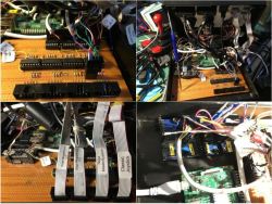
Wanting to keep the controllers unmodified — so they could still be used on the original systems — he had to do a bit of reverse-engineering and source some controller sockets before building his controller hub. Using shift-in registers, shift-out registers, and some multiplexers, he designed a large circuit selector — which acts as a shield for an Arduino Micro — so all the controllers remain connected. A potentiometer allows him to select the desired controller and a few arcade buttons which access RetroPie shortcuts really round out the hub. Check out the demo after the break!

Continue reading “Why Only Use One Controller When You Can Use ALL Of Them?”

Digging Deep Into How The 8085 Processor’s Registers Were Designed

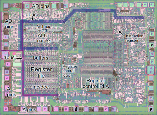
Hardware design enthusiasts should already be salivating just looking at this image. But [Ken Shirriff’s] write-up on how the 8085 processor’s registers were designed will put you in silicon reverse-engineering heaven. He manages to get to the bottom of the tricks the designers used to make register access as efficient as possible, like routing some through the ALU on their path elsewhere.

We’re certainly not experts in studying dies like the one seen above. Luckily [Ken] does a great job of zooming in on important parts, then dissecting how they work by representing the silicone image as a functional flow chart. One of the parts which we found most interesting is the WZ temporary registers. These are a set of internal registers that are not accessible to the programmer. They’re only used internally by the chip. They act as temporary storage for multiple operand functions, and also hold register addresses for a handful of instructions (JMP, CALL, RST, etc.).

If you’re more interested in how images of these chips are attained you should do some searching on Hackaday. Just last week we featured one such project in a links post.

[via Reddit]