Your home is your castle, and you are king or queen of all you survey. You’ve built your own home-automation system from scratch. Why would you possibly settle for the stock firmware in your robotic lawnmower? [Daniel Wiegert] wouldn’t either, so in Project Landlord he has started to reverse-engineer it.
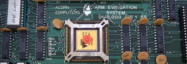
You can hardly blame him. The Worx Landroid‘s controller board uses an NXP LPC1768 ARM Cortex-M3, and the debug pins are labelled on the backside. The manufacturer didn’t protect the flash memory. It’s just begging to have its firmware dumped. So far, [Daniel] has managed to both brick and unbrick the device, and has completely mapped the controller’s pinout, so he’s on his way to complete control.
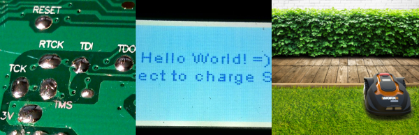
Right now, he’s got a working proof-of-concept firmware on his GitHub that’s able to drive the machine around a little bit and set the brakes. It’s running FreeRTOS, and [Daniel] is looking for other people to get in on the project. He’s done the hard initial work, so get in there and reap the rewards! Just don’t neglect to remove the blade before custom firmware.
Will custom firmware in a robotic lawnmower change the world? Probably not. But it is awesome, and will certainly make a difference in the lives of people whose robot mowers continually get stuck behind the hydrangeas.