You may not have heard, but there’s a chip shortage out there. And it’s not just the fancy new chips that are in short supply; the chips that were fancy and new back when you could still buy them from Radio Shack are getting hard to come by, too. For different reasons, of course, but it does pose a problem that requires a little hacking to fix.
The chip in question here is the General Instrument SP0256, a 1980s-era speech synthesizer chip that [Andrew Menadue] relies on. The LSI chip stored 59 unique allophones, or basic sounds the vocal tract is capable of, and synthesized speech by rapidly concatenating these sounds. The chip and its descendants made regular appearances in computers and games throughout the 80s, so chances are good you’ve heard it. If not, think WarGames (yes, we know that wasn’t actually a computerized voice) or [Stephen Hawking] and you’ll be pretty close.
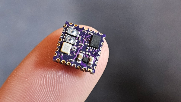
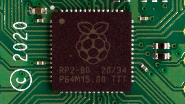
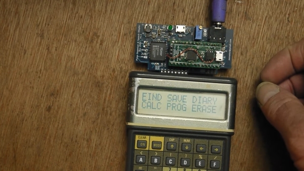
[Andrew]’s need for such a chip stems from his attempts to give voice to his collection of Psion Organisers, another 80s relic that was one of the first pocket computers. Some time ago he built a speech board for the Psion based on the SP0256-AL2, but had to resort to building an emulator for the chip since none were to be had. The emulator uses an RP2040 and lives on a PCB that has the same footprint as the original chip, so it can just plug right in. He dug up WAV files of the allophones and translated those to sequences of bytes, allowing the RP2040 to output the correct sounds as they’re called for. Speaker problems notwithstanding, it sounds pretty good in the video below.
We’ve featured a fair number of SP0256 projects before, on everything from Amstrad to Z80. We’ve also shown off a few of [Andrew]’s builds before, including this exploration of the voltage tolerance of the RP2040.
Continue reading “RP2040 Emulator Brings The Voice Of The 80s Back To Life”