Practical Sensors: The Hall Effect

Measuring a magnetic field can be very easy with some pretty low tech, or it can be very high tech. It just depends on what kind of measurement you need and how much effort you want to expend. The very simplest magnetic sensors are reed switches. These are basically relays with no coil. Instead of a coil, an external magnet gets close enough to make or break the contacts in the reed. You see these a lot in, for example, door alarm sensors.

Then again, there’s no real finesse to a reed. It changes state when it sees enough of a magnetic field and that’s about all. You could use a compass with some sort of detection on the needle to get some more information about the field, but not much more. That was, however, how early magnetometers worked. Today, you have lots of options, including the nearly ubiquitous Hall effect sensor.

You might use a Hall effect to measure the magnetic button on a keyboard key coming down when you press it or the open and closed state of a valve. A lot of Hall effects see service as current monitors. Since a coil generates a magnetic field proportional to the current through it, a magnetic sensor can estimate the current in a coil of wire without any physical contact. Hall effects can also watch a magnet go by in a linear motion system or a rotating system to get an idea of position or speed. For example, check out this brushless motor controller that uses three sensors to understand the motor’s position.

History

Edwin Hall identified the effect in 1879. The basic idea is simple: an electrical conductor carrying current will exhibit changes due to an external magnetic field nearby. These changes show up as voltage you measure across the conductor. Normally, the voltage across a conductor will be nearly zero, but with a magnetic field, you’ll get a non-zero reading in proportion to the magnetic field strength in a particular plane, as we’ll see shortly.

Hall effect sensors are just one type of modern magnetometer. There are many different kinds including those that use inductive pickup coils that may or may not rotate or a fluxgate, which is a special type of coil. Some use a scale or a spring to measure force against another magnet — sometimes microscopically. You can even detect a magnetic field using optical properties like the Kerr effect or Faraday rotation.

Continue reading “Practical Sensors: The Hall Effect”

Tightly Packed Raspberry Pi Tricorder Impresses

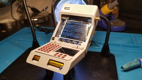
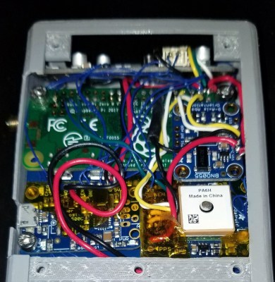
We’ll say upfront that we don’t have nearly as much information about this 3D printed Star Trek: The Next Generation tricorder as we’d like. But from the image galleries [Himmelen] has posted we know it’s running on the Raspberry Pi Zero W, has a color LCD in addition to a monochrome OLED, and that it’s absolutely packed with gear.

So far, [Himmelen] has fit an NESDR RTL-SDR dongle, a GPS receiver, an accelerometer, and the battery charging circuitry in the top half of the case. Calling it a tight fit would be something of an understatement, especially when you take into account all the wires snaking around in there. But as mentioned in the Reddit thread about the device, a custom PCB backplane of sorts is in the works so all these modules will have something a little neater to plug into.

There are a lot of fantastic little details in this build that have us very excited to see it cross the finish line. The female USB port that’s been embedded into the top of the device is a nice touch, as it will make it easy to add storage or additional hardware in the field. We also love the keyboard, made up of 30 individual tact switches with 3D printed caps. It’s hard to imagine what actually typing on such an input device would be like, but even if each button just fired off its own program or function, we’d be happy.

Judging by the fact that the LCD shows the Pi sitting at a login prompt in all the images, we’re going to go out on a limb and assume [Himmelen] hasn’t gotten to writing much software for this little gadget yet. Once the hardware is done and it’s time to start pushing pixels though, something like Pygame could be used to make short work of a LCARS-style user interface that would fit the visual style of The Next Generation. In fact, off the top of our heads we can think of a few turn-key projects out there designed for creating Trek UIs, though the relatively limited computational power of the Pi Zero might be a problem.

We’ve seen several projects that tried to turn the iconic tricorder into a functional device. Some have focused on the arguably more recognizable Next Generation style such as this one, and others have targeted the more forgiving brick-shaped unit from Kirk and Spock’s era. The Wand Company is even working on a officially licensed tricorder that will supposedly be as close to we can get to the real thing with modern tech and a $250 USD price tag, though we’d wager COVID has slowed progress down on that one. In any event, whether you build it or buy it, the tricorder seems destined to become reality before too long.

This Custom Dynamometer Is A Stirling Example Of Homebrewing

[Leo Fernekes] has fallen down the Stirling engine rabbit hole. We mustn’t judge — things like this happen in the best of families, after all. And when they do happen to someone like [Leo], things can get interesting mighty quickly.

His current video, linked below, actually has precious little to do with his newfound Stirling engine habit per se. But when you build a Stirling engine, and you’re of a quantitative bent, having some way to measure its power output would be handy. That’s a job for a dynamometer, which [Leo] sets out to build in grand fashion. Dynos need to measure the torque and rotational speed of an engine while varying the load on it, and this one does it with style.

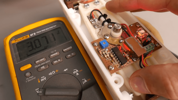
[Leo]’s torque transducer is completely DIY, consisting of hand-wound coils on the ends of a long lever arm that’s attached to the output shaft of the engine under test by a magnetic coupling. The coils are free to move within a strong magnetic field, with a PID loop controlling the current in the coils. Feedback on the arm’s position is provided by an optical sensor, also DIY, making the current necessary to keep the arm stationary proportional to the input torque. The video goes into great detail and has a lot of design and build tips.

We just love the whole vibe of this build. There may have been simpler or quicker ways to go about it, but [Leo] got this done with what he had on hand for a fraction of what buying in off-the-shelf parts would have cost. And the whole thing was a great learning experience, both for him and for us. It sort of reminds us of a dyno that [Jeremy Fielding] built a while back, albeit on a much different scale.

Continue reading “This Custom Dynamometer Is A Stirling Example Of Homebrewing”

Magnetic Angle Sensor Mods Make Encoder Better For Blasting

Most of the hacks we see around these parts have to do with taking existing components and cobbling them together in interesting new ways. It’s less often that we see existing components gutted and repurposed, but when it happens, like with this reimagined rotary encoder, it certainly grabs our attention.

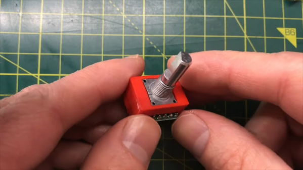
You may recall [Chris G] from his recent laser-based Asteroids game. If not you should really check it out — the build was pretty sweet. One small problem with the build was in the controls, where the off-the-shelf rotary encoder he was using didn’t have nearly enough resolution for the job. Rather than choosing a commodity replacement part, [Chris] rolled his own from the mechanical parts of the original encoder, like the shaft and panel bushing, and an AS5048A sensor board. The magnetic angle sensor has 14 bits of resolution, and with a small neodymium ring magnet glued to the bottom of the original shaft, the modified encoder offers far greater resolution than the original contact-based encoder.

The sensor breakout board is just the right size for this job; all that [Chris] needed to do to get the two pieces together was to 3D-print a small adapter. We have to admit that when we first saw this on Hackaday.io, we failed to see what the hack was — the modified part looks pretty much like a run-of-the-mill encoder. The video below shows the design and build process with a little precision rock blasting.

Continue reading “Magnetic Angle Sensor Mods Make Encoder Better For Blasting”

Simple Sensor Makes Filament Measurements A Snap

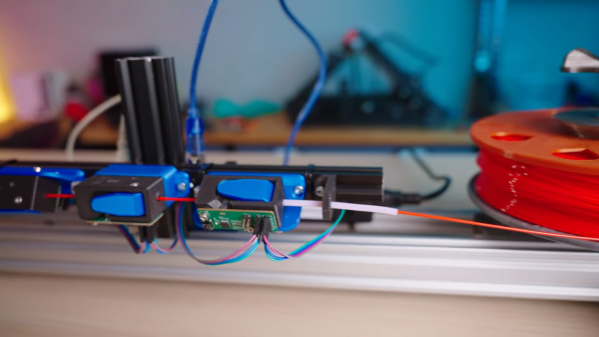
Just how tight are the manufacturing tolerances of modern FDM printer filament. Inquiring minds want to know, and when such minds are attached to handy fellows like [Thomas Sanladerer], you end up with something like this home-brew filament measurement rig to gather the data you seek.

The heart of this build is not, as one might assume, some exotic laser device to measure the diameter of filament optically. Those exist, but they are expensive bits of kit that are best left to the manufacturers, who use them on their production lines to make sure filament meets their specs. Rather, [Thomas] used a very clever homemade device, which relies on a Hall effect sensor and a magnet on a lever to do the job. The lever is attached to a roller bearing that rides on the filament as it spools through the sensor; variations in diameter are amplified by the lever arm, which wiggles a magnet over the Hall sensor, resulting in a signal proportional to filament diameter.

The full test rig has a motor-driven feed and takeup spools, and three sensors measuring across the filament in three different spots around the radius; the measurements are averaged together to account for any small-scale irregularities. [Thomas] ran several different spools representing different manufacturers and materials through the machine; we won’t spoil the results in the video below, but suffice it to say you probably have little to worry about if you buy from a reputable vendor.

When we see a filament sensor, it’s generally more of the “there/not there” variety to prevent a printer from blindly carrying on once the reel is spent. We’ve seen a few of those before, but this is a neat twist on that concept.

Continue reading “Simple Sensor Makes Filament Measurements A Snap”

Implementing SENT Sensors On The Raspberry Pi

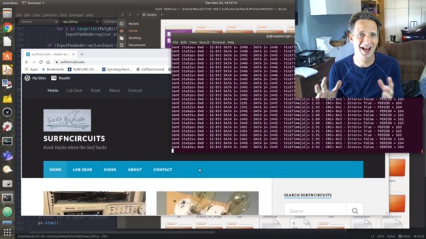
The SENT protocol, standing for Single Edge Nibble Transmission, is used for sensors that need to send high-resolution data while keeping system costs low. It’s most typically used in the automotive world, where it can be found in such parts as throttle-by-wire pedals and temperature sensors. [Mark Smith] set out to see if he could get the Pi Zero to read such sensors without the use of an intermediate microcontroller.

[Mark]’s initial attempts relied on Python and the RPI.GPIO library. Unfortunately, the overheads introduced made decoding SENT traffic impossible. Undeterred, [Mark] pressed on, leveraging the pigpio library and its callback function which allowed sampling at up to one microsecond. This was fast enough to read the messages from a LX3302A inductive position sensor that uses the protocol.

It’s a project that could prove useful for those trying to work with certain sensors who want to avoid adding complexity to a Raspberry Pi project. Files are available on Github for the curious. We’ve seen other direct sensor builds with the Pi, before too – like this power monitoring system. Video after the break.

Continue reading “Implementing SENT Sensors On The Raspberry Pi”

Pulse Oximetry Sensor Judges Your Coffee Roast

Breakout board for the MAX30101, which [Zach] used as the basis of his roast gauge. The sensor is at the top edge of the board.
Parts designed and marketed for a specific application can nevertheless still be useful in other ways, and whenever that happens, it’s probably the start of a pretty good hack. Using a sensor for something other than its intended purpose is exactly what [Zach Halvorson] did to make the Roast Vision device, which uses the MAX30101, a sealed optical sensor intended mainly for pulse oximetry and heart-rate monitoring.

[Zach] is instead using that sensor to measure the roast level of coffee beans, and assign a consistent number from 0 to 35 to represent everything from Very Dark to Very Light. Measuring a bean’s roast level is important to any roaster seeking accuracy and consistency, but when [Zach] found that commercial roast gauges could easily cost over a thousand dollars, he was sure he could do better.

[Zach] settled on using a Sparkfun MAX30101 breakout board to develop his device, and Sparkfun shared an informative blog post that demonstrates how making hardware and tools more accessible can help innovative ideas flourish. The Roast Vision device has a 3D printed enclosure, and a simple top-loading design with an integrated sample cup makes it easy to use. One simply puts about a teaspoon of finely-ground coffee into the sample cup, and the unit provides a measurement in a couple of seconds. Fortunately the sensor works just fine though an acrylic window which means the device can be sealed; a handy feature for a tool that will spend a lot of time around ground coffee.

The joys of fresh roasted coffee is something that is perfectly accessible to those making small batches at home. There are commercial options for small roasters of course, but should you wish to go the DIY route, check out our own Elliot Williams’ guide on making a low-cost DIY roaster.