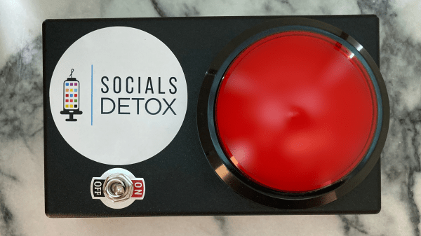
Dangerous machines, like ones that can quickly reduce you to a fine red mist or a smoking cinder, tend to have a Big Red Button™ to immediately stop whatever the threat is. Well, if a more dangerous machine than social media has ever been invented, we’re not sure what it would be, which is why we’re glad this social media kill switch exists.
The idea behind [Gunter Froman]’s creation is to provide a physical interface to SocialsDetox, a service that blocks or throttles connectivity to certain apps and websites. SocialDetox blocks access using either DNS over HTTPS (DoH) or, for particularly pesky and addictive apps, a service-specific VPN. The service does require a subscription, the cost of which varies by the number of devices you want to protect, but the charges honestly seem pretty reasonable.
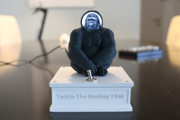
While SocialsDetox can be set up to block access on a regular schedule, say if you want to make the family dinner a social-free time, there may be occasions where killing social access needs to happen right now. This is where the Big Red Button comes into it, which is attached to a Wemos D1 Mini. Pressing the kill switch sends an API request to either enable or disable the service, giving you a likely much-needed break from the swirling vortex of hate and envy that we all can’t seem to live without. Except for Hackaday, of course — it’s totally not like that here.
The irony of using an IoT appliance to restrict access to social media is not lost on us, but you work with the tools you’ve got. And besides, we like the physical interface here, which sort of reminds us this fitting enclosure for a PiHole.