Robust I2C And SPI In Space Thanks To Bus Isolation

Imagine you’re sending a piece of hardware to space on a satellite. Unless you’re buddy-buddy with NASA, it’s pretty unlikely you’ll ever be able to head up there and fix something if it goes wrong once it’s launched. Robust design is key, so that even in the event of a failure in one component, the rest of the hardware can keep working.

The example I2C isolation circuit from [Max’s] paper. The SPI implementation is even simpler.
[Max Holliday] found himself in this exact situation, running 69 I2C and SPI devices in a single satellite. Thus, he came up with circuits to auto-isolate devices from these buses in the event of an issue. That work is the subject of a research paper now available on the TechRxiv Preprint Server.

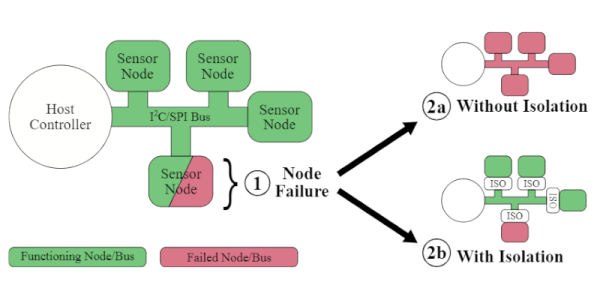
The problem is that these simple buses aren’t always the most robust, being vulnerable to single-point failures where one bad part takes down other parts of the bus. [Max] notes that vast numbers of sensors and devices rely on these standards, and it can be difficult or prohibitively expensive to design without them, so a solution was needed.

To fix this, [Max] developed a simple external circuit that could be placed on each node of a I2C or SPI communication bus. In the event of malfunction, that node can be cut off from the bus by this circuit, allowing the rest of the system to go on functioning.

With little more than a few transistors, MOSFETs and passives, you too could protect your buses from malfunctions using these techniques. [Max] did just that on the NASA V-R3x mission which flew successfully in January 2021 if you needed any further confirmation of the value of this technique.

It’s something that won’t bother the home hobbyist building a garage door opener, but it could be of great value to those designing systems that must fail gracefully if they fail at all. Be sure to share your best tips and tricks for robust SPI and I2C buses in the comments below!
Taking A Deep Dive Into SPI

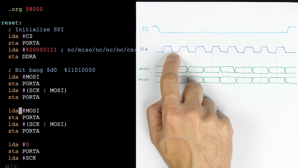
With the prevalence of libraries, it has never been easier to communicate with hundreds of different sensors, displays, and submodules. But what is really happening when you type SPI.begin() into the Arduino IDE? In his most recent video, [Ben Eater] explores the Serial Peripheral Interface (SPI) and how it really works.

Most Hackaday readers probably know [Ben] from his breadboard-based computers, such as the 6502 build we featured in 2019. Since then he has been hard at work, adding new and interesting additions to his breadboard computer, as well as diving into different communication protocols to better understand and implement them. For this video, [Ben] set the goal of connecting the BME280, a common pressure, temperature, and humidity sensor with an SPI interface, to his breadboard 6502 computer. Along the way, [Ben] discusses how exactly SPI works, and why there is so much conflicting nomenclature and operations when looking at different SPI devices.

If breadboard computers aren’t your thing, there are tons of other uses for the BME280, such as helping to modernize a Casio F-91W.

Continue reading “Taking A Deep Dive Into SPI” →

Camera Hack Peels Back Layers Of Embedded Linux

Embedded Linux devices are everywhere these days, and sooner or later, you’re going to want to poke around in one of them. But how? That’s where posts like this one from [Felipe Astroza] come in. While his work is focused on the Foscam C1 security camera, the techniques and tools he outlines here will work on all sorts of gadgets that have a tiny penguin at their core.

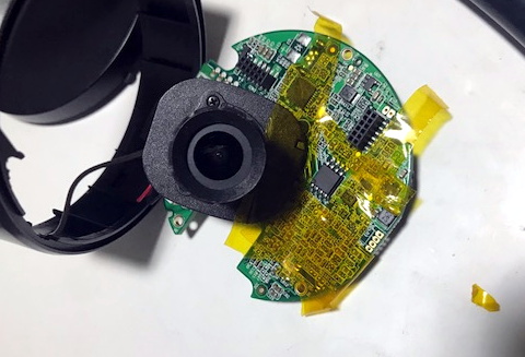
Rather than trying to go in through the front door, [Felipe] starts his assault with the nuclear option: removing the SPI MX25L12835F flash chip from the camera’s PCB and dumping its contents with a Raspberry Pi. From there he walks through the use of different tools to determine the partition scheme of the chip and eventually extract passwords and other interesting bits of information from the various file systems within.

Getting ready to remove the flash chip.

That alone would be worth the read, but things really get interesting once [Felipe] discovers the FirmwareUpgrade program. Since the Foscam’s software updates are encrypted, he reasons that reverse engineering this binary would uncover the key and allow for the creation of custom firmware images that can be flashed through the stock interface.

Further investigation with Ghidra and friends identifies an interesting shared library linked to the executable in question, which is then disassembled in an effort to figure out how the key is being obfuscated. We won’t ruin the surprise, but [Felipe] eventually gets what he’s after.

This isn’t the first time [Felipe] has played around with the firmware on these Internet connected cameras, and we dare say it won’t be his last. For those who are really into tinkering with these sort of devices, it’s not unheard of to install a socket for the flash chip to make software modifications faster and easier.

Bridging The PC And Embedded Worlds With Pico And Python

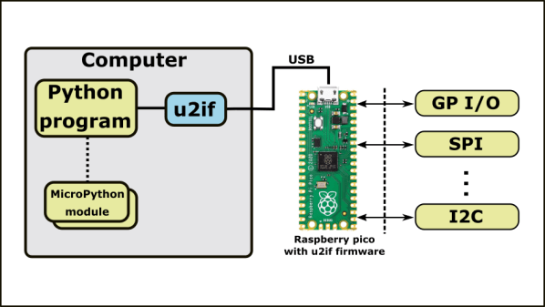
Although protocols like I2C and SPI are great for communicating between embedded devices and their peripherals, it can be a pain to interface these low-level digital interfaces to a PC. [Alexandre] typically used an Arduino to bridge between the PC and embedded worlds, but he got tired of defining a custom serial protocol for each project. Inspired by MicroPython’s machine module, [Alexandre] has developed u2if—an implementation of some of MicroPython’s machine module for PC—using a USB-connected Raspberry Pi Pico to bridge between a PC and low-level digital interfaces.

u2if consists of two parts: the PC portion is a Python implementation of a portion of the MicroPython machine module, and the Raspberry Pi Pico receives some custom C++ firmware. Thus far, [Alexandre] has implemented functionality for the onboard ADCs, I2C, SPI, UART, and GPIO lines as well as additional support for I2S sound and the WS2812B addressable LED.

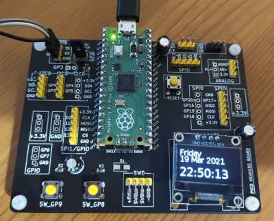
Development board for Raspberry Pi Pico.

In addition to the u2if package, [Alexandre] has designed a PCB to break out all of the Raspberry Pi Pico’s interfaces in a handy 3×3.9″ board. We especially like that multiple headers are supplied for I2C, including one with enough space to mount an SSD1306 OLED display.

We think this could be an incredibly useful tool, and what makes it even more impressive is that it uses a board many of us already have laying around. If you want a dedicated device for interfacing with low-level digital buses, you may want to check out the GreatFET.

Arduboy FX Mod-Chip: Now You’re Playing With Power

Traditionally, a forum full of technical users trying integrate their own hardware into a game system for the purposes of gaining unfettered access to its entire software library was the kind of thing that would keep engineers at Sony and Nintendo up at night. The development and proliferation of so called “mod chips” were an existential threat to companies that made their money selling video games, and as such, sniffing out these console hackers and keeping their findings from going public for as long as possible was a top priority.

But the Arduboy is no traditional game system. Its games are distributed for free, so a chip that allows users to cram hundreds of them onto the handheld at once isn’t some shady attempt to pull a fast one on the developers, it’s a substantial usability improvement over the stock hardware. So when Arduboy creator Kevin Bates found out about the grassroots effort to expand the system’s internal storage on the official forums, he didn’t try to put a stop to it. Instead, he asked how he could help make it a reality for as many Arduboy owners as possible.

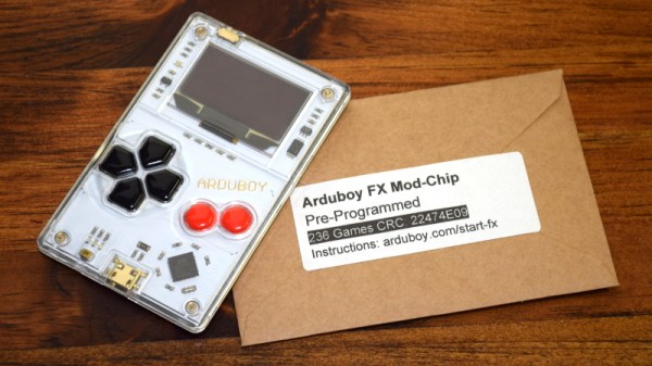
Now, a little less than three years after forum member Mr.Blinky posted his initial concept for hanging an external SPI flash chip on the system’s test pads, the official Arduboy FX Mod-Chip has arrived. Whether you go the DIY route and build your own version or buy the ready-to-go module, one thing is for sure: it’s a must-have upgrade for the Arduboy that will completely change how you use the diminutive handheld.

Continue reading “Arduboy FX Mod-Chip: Now You’re Playing With Power” →

Logic Meter Aims To Make Hobby Electronics Troubleshooting Easier

The basic test instrument suite — a bench power supply, a good multimeter and perhaps an oscilloscope — is extremely flexible, but not exactly “plug and play” when it comes to diagnosing problems with some common hardware setups. A problem with a servo driver, for example, might be easy enough to sort of with a scope, but setting everything up to see what’s going on with the PWM signal takes some time.

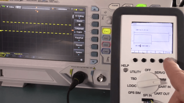
There’s got to be a better way to diagnose hobby electronics woes, and if [Bob Alexander] has his way, his “Logic Meter”, or something very close to it, will be the next must-have bench tool. The Logic Meter combines some of the functionality of an oscilloscope and a logic analyzer into a handy instrument that’s as easy to use as a multimeter. The Logic Meter’s probes connect to logic-level signals in a circuit and can be set up to capture or send serial data, either directly to or from a UART or via an SPI bus connection. There are also functions for testing servos and similar devices with a configurable PWM output. [Bob] rounds out the functionality with a GPS simulator and a simple logic analyzer, plus some utility functions.

The beauty part of the Logic Meter is that [Bob] has left where it goes next largely up to the community. He’s got a GitHub repo with details on the PIC32-based hardware, and the video below makes it clear that this is just a jumping-off point to further work that he hopes results in a commercial version of the Logic Meter. That’s a refreshing attitude, and we hope it pays off; from the look of a few of [Bob]’s retrocomputing makeovers, something like the Logic Meter could come in pretty handy.

Continue reading “Logic Meter Aims To Make Hobby Electronics Troubleshooting Easier” →

A Novel Micro Desktop Display For Your Raspberry Pi

Since its debut back in 2012 there have been a variety of inventive displays used with the Raspberry Pi. Perhaps you remember the repurposed Motorola phone docks, or you have one of those little displays that plugs into the expansion port. Inevitably the smaller options become disappointing as desktop displays, because while the advert triumphantly shows them sporting a Raspberry Pi OS desktop the reality is almost unusable. Until now.

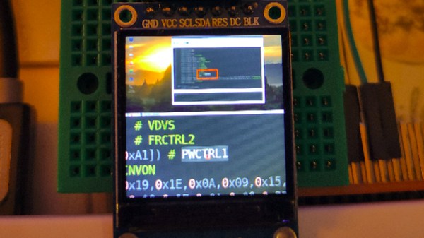
Along comes [igbit] with a solution in the form of a little SPI display with a different approach to displaying a desktop. Instead of displaying a matchbox-sized desktop over the whole screen it divides into two halves. At the top is a representation of the desktop, while below it is a close-up on the area around the mouse pointer.

Unexpectedly its mode of operation is very accessible to the non-Linux guru, because it works through a Python script that takes screenshots of both areas and passes them as a composite to the display. An area the size of the magnified window is drawn around the mouse pointer, allowing it to be easily located on the tiny desktop. It relies on the main display being pushed to the HDMI output, so if the Pi is otherwise headless then its configuration has to be such that it forces HDMI use. The result isn’t something that would help you with the more demanding desktop tasks, but it provides a neat solution to being able to use a Pi desktop on a tiny screen.

Of course, in a pinch you can always use your mobile phone.