We’re not entirely sure what to call this one. It’s got the usual trappings of a drone, but with only a single rotor it clearly can’t be called by any of the standard multicopter names. Helicopter? Close, but not quite, since the rotor blades are fixed-pitch. We’ll just go with “monocopter” for now and sort out the details later for this ducted-fan, thrust-vectored UAV.
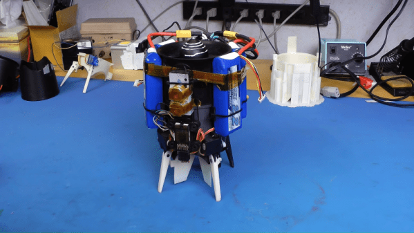
 Whatever we choose to call it — builder [tesla500] dubbed it the simultaneously optimistic and fatalistic “Ikarus” — it’s really unique. The monocopter is built around a 90-mm electric ducted fan mounted vertically on a 3D-printed shroud. The shroud serves as a mounting point for the landing legs and for four servos that swivel vanes within the rotor wash. The vanes deflect the airstream and provide the thrust vectoring that gives this little machine its control.
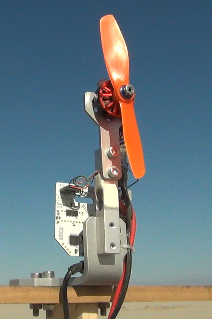
Coming to the correct control method was not easy, though. Thanks mainly to the strong gyroscopic force exerted by the rotor, [tesla500] had a hard time getting the flight controller to cooperate. He built a gimballed test stand to work the problem through, and eventually rewrote LibrePilot to deal with the unique forces on the craft and tuned the PID loops accordingly. Check out the results in the video below.
Some attempts to reduce the number of rotors work better than others, of course, but this worked out great, and we’re looking forward to the promised improvements to come.
Continue reading “Single-Rotor Drone: A Thrust-Vectoring Monocopter”
 We’ve probably all experimented with a very clear demonstration of the basic principles of lift: if you’re riding in a car and you put your flattened hand out the window at different angles, your hand will rise and fall like an airplane’s wing, or airfoil. This week’s Retrotechtacular explains exactly how flight is possible through the principles of lift and drag. It’s an Army training documentary from 1941 titled “
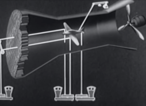
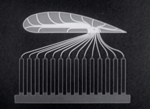 Airfoil models are also unit tested in wind tunnels. They are built with small tubes running along many points of the foil that sit just under the surface. The tubes leave the model at a single point and are connected to a bank of manometer tubes. These tubes compare the pressures acting on the airfoil model to the reference point of atmospheric pressure. The different liquid levels in the manometer tubes give clear proof of the pressure values along the airfoil. These levels are photographed and mapped to a pressure curve. Now, a diagram can be made to show the positive and negative pressures relative to the angle of attack.


