A tool breaking in the midst of a CNC machining operation is always a disaster. Not only do you have a broken tool (no small expense), but if the program continues to run there is a good chance it’ll end up ruining your part too. In particularly bad cases, it’s even possible to for this to damage the machine itself. However, if the breakage is detected soon enough, the program can be stopped in time to salvage the part and avoid damage to your machine.
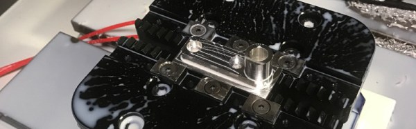
Many new machining centers have the ability to automatically detect tool breaks, but this is a feature missing from older machines (and inexpensive modern machines). To address this issue, [Wiley Davis] came up with a process for adding broken tool detection to an older Haas mill. The physical modifications are relatively minor: he simply added a limit switch wired to the existing (but unused) M-Function port on the Haas control board. This port is used to expand the functionality of the machine, but [Wiley] didn’t need it anyway.
If you are reading this, it is a fair bet you like to take things apart. Sometimes, you even put them back together. There are two bad moments that can occur when you do this. First, when you get done and there is some stuff left over. That’s usually not good. The other problem is when you are trying to find some little tiny bolt and a washer and you can’t find it. SMD parts are especially easy to lose.
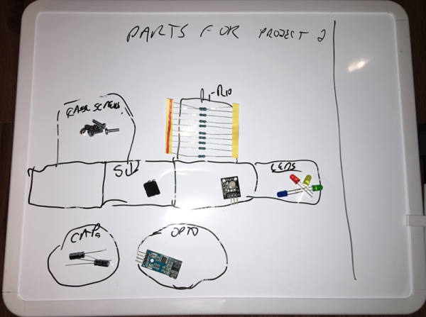
A few months ago, I was browsing through a local store and I saw a neat idea. It was basically a small whiteboard with lines dividing it into cells. It was magnetic and the idea is you’d put your small loose (and ferrous) parts like screws, bolts, nuts, and resistors on the board. Since it was a marker board, you could make notes about what each cell contained. Great idea! But the thing was about $20 and I thought I could do better than that. As you might guess from the picture, I was successful. I spent about $5, although I had some rare-earth magnets hanging around. If you don’t, strong magnets aren’t that expensive and you can often raid them out of hard drives.
Sometimes, the appropriate application of force is the necessary action to solve a problem. Inelegant, perhaps, but bending a piece of metal with precision is difficult without a tool for it. That said, where a maker faces a problem, building a solution swiftly follows; and — if you lack a metal brake like YouTuber [makjosher] — building one of your own can be accomplished in short order.
Drawing from numerous online sources, [makjosher]’s brake is built from 1/8″ steel bar, as well as 1/8″ steel angle. The angle is secured to a 3/4″ wood mounting plate. Displaying tenacity in cutting all this metal with only a hacksaw, [makjosher] carved slots out of the steel to mount the hinges, which were originally flush with the wood. He belatedly realized that they needed to be flush with the bending surface. This resulted in some backtracking and re-cutting. [Makjosher] then screwed the pivoting parts to the wood mount. A Box tube serves as a handle. A coat of paint finished the project, and adding another tool to this maker’s kit.
When working on a new project, it’s common to let feature creep set in and bloat the project. Or to over-design a project well beyond what it would need to accomplish its task. Over at Black Mesa Labs, their problem wasn’t with one of their projects, it was with one of their tools: their hot plate. For smaller projects, an 800W hot plate was wasteful in many ways: energy, space, and safety. Since a lot of their reflow solder jobs are on boards that are one square inch, they set out to solve this problem with a tiny hot plate.
The new hot plate is perfectly sized for the job. Including control circuitry, it’s around the size of a credit card. The hot plate is powered from a small surplus 20V 5A laptop power supply and does a nice 4 minute reflow profile and cools off completely in under a minute. Compared to their full-sized hot plate, this is approximately 29 minutes faster, not to mention the smaller workspace footprint that this provides. The entire setup cost about $20 from the heating element to the transistors and small circuit board, and assuming that you have an Arduino Pro sitting in your junk bin.
It’s a good idea to have a reflow oven or a hot plate at your disposal, especially if you plan to do any surface mount work. There are lots of options available, from re-purposed toaster ovens to other custom hot plates of a more standard size. Overkill isn’t always a bad thing!
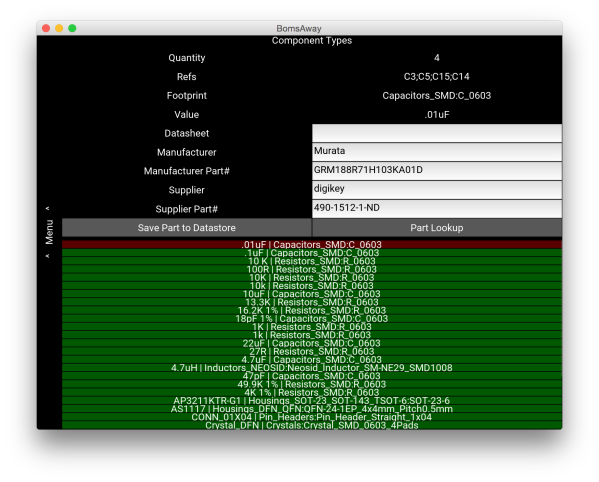
KiCAD remains a popular tool for designing PCBs and other circuits, and with good reason: it’s versatile and it’s got pretty much everything needed to build any type of circuit board you’d want. It also comes with a pretty steep learning curve, though, and [Jeff] was especially frustrated with the bill of materials (BOM) features in KiCAD. After applying some Python and Kivy, [Jeff] now has a BOM manager that makes up for some of KiCAD’s shortcomings.
Currently, the tool handles schematic import, like-component consolidation, and a user-managed parts database that can be used to store and retrieve commonly used parts for the future. All of the changes can be saved back to the original schematic. [Jeff] hopes that his tool will save some time for anyone who makes more than one PCB a year and has to deal with the lack of BOM features native to KiCAD.
[Jeff] still has some features he’d like to add such as unit tests, a user guide, and a cleaner user interface. What other features are you anxious to see added to KiCAD?
My printer has other issues that I’m still tuning out, but the warping in PLA and excessive surface roughness has all the signs of over extrusion.
I have an old Prusa i2 that, like an old car, has been getting some major part replacements lately after many many hours of service. Recently both the extruder and the extruder motor died. The extruder died of brass fill filament sintering to the inside of the nozzle (always flush your extruder of exotic filaments). The motor died at the wires of constant flexing. Regardless, I replaced the motors and found myself with an issue; the new motor and hotend (junk motor from the junk bin, and an E3D v6, which is fantastic) worked way better and was pushing out too much filament.
The hotend, driver gear, extruder mechanics, back pressure, motor, and plastic type all work together to set how much plastic you can push through the nozzle at once. Even the speed at which the plastic is going through the nozzle can change how much friction that plastic experiences. Most of these effects are somewhat negligible. The printer does, however, have a sort of baseline steps per mm of plastic you can set.
The goal is to have a steps per mm that is exactly matched to how much plastic the printer pushes out. If you say 10mm, 10mm of filament should be eaten by the extruder. This setting is the “steps per mm” in the firmware configuration. This number should be close to perfect. Once it is, you can tune it by setting the “extrusion multiplier” setting in most slicers when you switch materials, or have environmental differences to compensate for.
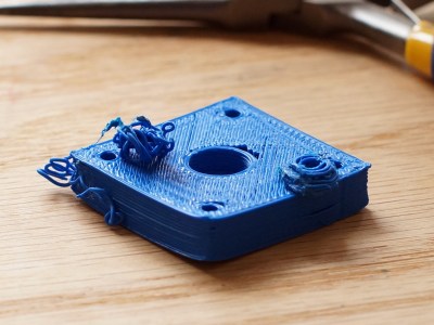
This little guy lets you tune the steps per mm exactly.
The problem comes in measuring the filament that is extruded. Filament comes off a spool and is pulled through an imprecisely held nozzle in an imprecisely made extruder assembly. On top of all that, the filament twists and curves. This makes it difficult to hold against a ruler or caliper and get a trustworthy measurement.
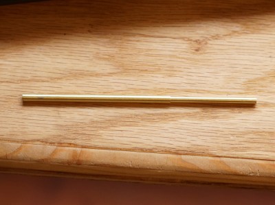
I have come up with a little measuring device you can make with some brass tubing, sandpaper, a saw (or pipe cutter), a pencil torch, solder, and some calipers. To start with, find two pieces of tubing. The first’s ID must fit closely with the filament size you use. The second tube must allow the inside tubing to slide inside of it closely. A close fit is essential.
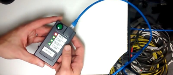
If you’re a networking professional, there are professional tools for verifying that everything’s as it should be on the business end of an Ethernet cable. These professional tools often come along with a professional pricetag. If you’re just trying to wire up a single office, the pro gear can be overkill. Unless you make it yourself on the cheap! And now you can.
What’s going on under the hood? A Raspberry Pi, you’d think. A BeagleBoard? Our hearts were warmed to see a throwback to a more civilized age: an ENC28J60 breakout board and an Arduino Uno. That’s right, [Kristopher] replicated a couple-hundred dollar network tester for the price of a few lattes. And by using a pre-made housing, [Kristopher]’s version looks great too. Watch it work in the video just below the break.