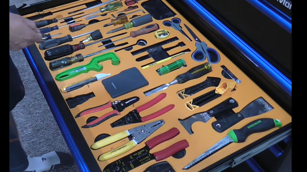
Helium Recovery System Saves Costs

Helium is the most common element in the universe besides hydrogen, but despite this universal abundance it is surprisingly difficult to come across on Earth. Part of the problem is that it is non-renewable, so unless it is specifically captured during mining its low density means that it simply escapes the atmosphere. For that reason [Meow] maintains a helium recovery system for a lab which is detailed in this build.

The purpose of the system is to supply a refrigerant to other projects in the lab. Liquid helium is around 4 Kelvin and is useful across a wide variety of lab tests, but it is extremely expensive to come across. [Meow]’s recovery system is given gaseous helium recovered from these tests, and the equipment turns it back into extremely cold liquid helium in a closed-cycle process. The post outlines the system as a whole plus goes over some troubleshooting that they recently had to do, and shows off a lot of the specialized tools needed as well.

Low-weight gasses like these can be particularly difficult to deal with as well because their small atomic size means they can escape fittings, plumbing, and equipment quite easily compared to other gasses. As a result, this equipment is very specialized and worth a look. For a less lab-based helium project, though, head on over to this helium-filled guitar instead.

Internal Combustion Torque Monster Has Great Impact

Once the domain of automotive repair shops and serious hobbyists with air compressors, the impact driver so famously used to remove and install wheel lug nuts and other Big Fasteners with just a squeeze of the trigger is more accessible than ever. Thanks to Lithium Ion batteries and powerful and compact brushless motors, you can now buy a reasonably powerful and torquey impact driver for a relatively low price- no air compressor needed! But what if you relish the thought of a noisy, unwieldy and unnecessarily loud torque monster? Then the video below the break by [Torque Test Channel] is just what you need!

Now, this is Hackaday, so we don’t have to go into detail about why a person might want to rip out the electric motor and adapt a 60cc 2 stroke engine in its place. Of course that’s the obvious choice. But [Torque Test Channel] isn’t just mucking about for the fun of it. No, they’re having their fun, experimenting with internal combustion engines in odd places before they are banned by 2024 in California. Now, we’re not sure if the ban includes these exact types of engines- but who needs details when you have an impact driver that can change semi tires like a NASCAR pit crew.

Looking like an overpowered weapon from a first person shoot’em up game, [Torque Test Channel]’s modified Milwaukee tests well after some modifications. Be sure to watch the video to see how it performs against an electric tool that’s even larger than itself. There are graphs, charts, and an explanation of what can be done to make even more power in the future. We’re looking forward to it!

What’s that you say? You don’t have a two stroke engine sitting around waiting to be swapped into ridiculous gadgets? Look no further than your local fridge compressor and be ready to burn some hours getting it running.

Continue reading “Internal Combustion Torque Monster Has Great Impact”

Pressure Gauge Built In A Vacuum

Necessity might be the mother of all invention, but we often find that inventions around here are just as often driven by expensive off-the-shelf parts and a lack of willingness to spend top dollar for them. More often than not, we find people building their own tools or parts as if these high prices are a challenge instead of simply shrugging and ordering them from a supplier. The latest in those accepting the challenge of building their own parts is [Advanced Tinkering] who needed a specialty pressure gauge for a vacuum chamber.

In this specific case, the sensor itself is not too highly priced but the controller for it was the deal-breaker, so with a trusty Arduino in hand a custom gauge was fashioned once the sensor was acquired. This one uses an external analog-to-digital converter to interface with the sensor with 16-bit resolution, along with some circuitry to bring the ~8 V output of the sensor down to the 5 V required by the microcontroller. [Advanced Tinkering] wanted a custom live readout as well, so a 3D printed enclosure was built that includes both an LCD readout of the pressure and a screen with a graph of the pressure over time.

For anyone else making sensitive pressure measurements in a vacuum chamber, [Advanced Tinkering] made the project code available on a GitHub page. It’s a great solution to an otherwise overpriced part provided you have the time to build something custom. If you’re looking for something a little less delicate, though, take a look at this no-battery pressure sensor meant to ride along on a bicycle wheel.

Continue reading “Pressure Gauge Built In A Vacuum”

One Tool Twists Wires, And Skewers Shish Kebabs

Twisting stranded wire with your fingers in preparation for tinning and/or soldering is almost a reflex for folks making electronic assemblies. But what if the wires are too close to get your fingers around, or you have the fingers of a sumo wresters? Well [DIYDSP] has a solution for you (see video below the break) that’s easy to make from a shish kebab skewer that’s probably rolling around your kitchen drawer. The reason that [DIYDSP] wanted to twist such closely spaced wires was to solder a length of 0.1 in O.C. stranded ribbon cable directly onto a PCB pin header pattern.

The method is very simple. Drill a long hole in the factory-cut flat end, followed by using a countersink bit to give a conical taper to guide the wires in. [DIYDSP] found that a 1/16 inch (1.6 mm) drill bit was a bit too large to grip the types of wires he was using, and finally settled on a 0.6 mm bit. If you are using larger wires, you should experiment to get the right size, or just build a handful of these of differing diameters since they’re so easy to make — just mark them clearly so you don’t accidentally grill shish kebabs with them on the BBQ.

The resulting tool is not unlike the business end of a hand-held wire-wrap tool, but works different principle and is a fraction of the cost. If you do any amount of interconnect wiring with stranded wires, then you should check out this video and whip up a couple of these to throw in your tool box.

Continue reading “One Tool Twists Wires, And Skewers Shish Kebabs”

Building A Custom Branding Iron With Swappable Date Blocks

Branding can be done on wood with just about any old bit of hot metal, but if you want to do it well, properly-crafted tooling will go a long way. [Wesley Treat] has built just that with this modular branding iron design.

The branding tooling itself is machined out of brass on an X-Carve CNC router, using [Wesley]’s own logo. The part is sanded after machining to remove tooling marks. A smaller brass slug is then machined with the numerals for various years with which [Wesley] may wish to stamp his projects.

Rather than hacking something sloppy together, the iron itself is assembled with a beautifully wood-turned handle of his own creation and a steel backing plate to hold the tooling. The date is separately removable from the main logo itself for easy changes in future. Naturally, the tool graphics are done in reverse so as to register the right way around when burned onto wood.

The tool is used with a torch to heat the brass up such that it can leave its impression on wooden surfaces. The final results are solid, if not quite perfect; getting the temperature across the tool perfectly matched would be key to getting the cleanest results. An electric heating element running in closed loop could be a way to achieve this.

Fundamentally, it’s a tidy way to mark your wooden projects in a hurry. We’ve seen wood burning reach even greater heights, too, such as with this CNC pyrography machine. Video after the break.

Continue reading “Building A Custom Branding Iron With Swappable Date Blocks”

File testing rig

Science Vs Internet Trolls: Testing Another Kind Of File System

No matter what you do or say on the Internet, you’re always doing it wrong. Keyboard commandos are ready to pounce and tell you how it’s “ackchyually” supposed to be done. And so it was of little surprise when [Jason] of Fireball Tools was taken to task by the armchair millwright for his supposedly deficient method of filing metal.

But [Jason] chose to fight back not with words but deeds, building a system to test alternative methods of filing. His filing style is to leave the file in contact with the stock on both the front- and back-strokes, which enraged those who claim that a file must never be dragged back over the workpiece, lest the teeth become dull. The first video below shows the build of the test rig, which leveraged his enormous Cinncinatti shaper as the prime mover, as well as a pneumatic jig to hold the workpiece and imitate both styles of filing. Part two below shows the test rig in action, and [Jason] really outdoes himself with his experimental approach. He tested three different grades of Pferd files — nothing but the best, no expense spared — and did duplicates of each run using both the Internet-approved style and his lazier style.

The result? We won’t spoil that for you, but suffice it to say that the hive mind isn’t always right. And what’s more, [Jason]’s careful myth-busting yielded a few interesting and unexpected results. His channel is full of great shop tips and interesting builds, so check him out if you want to see how metalworking is done.

Continue reading “Science Vs Internet Trolls: Testing Another Kind Of File System”

Copper tubes formed by 3D printed press dies

Can 3D Printed Press Tools Produce Repeatable Parts?

When we think of using a press to form metal we think of large stamps with custom made metal dies under unimaginable hydraulic pressure. It’s unlikely we’d e think of anything 3D printed. And in a commercial environment we’d be right. But your average garage hacker is far more likely to have access to a bench vise and a 3D printer. It’s in this context that [The Shipping Container Garage] has spent considerable time, effort, and money perfecting a process for pressing copper parts with 3D printed dies, which you can watch below the break.

In the quest to make a custom intake manifold for his project car, [The Shipping Container Garage] first made 3D printed jigs for cutting out a manifold flange that bolts to the cylinder head. It’s a process he calls Analog CNC, as all the cutting is done by hand.

Buoyed by his success, he proceeded with the next step: making manifold runners. His metal of choice was copper. While softer than many metals such as steel, he found it too hard. In the video, he describes his method for annealing the copper. Once cooled, two 3D printed dies are pressed into the copper tubes to progressively shape them. Watch the video to find out one of the neatest details of the die itself: how he gets it out!

Of course no matter how clever this all is, it’s useless if it produces poor results. And that’s where the most astounding part of the build is: The parts are all the same within 0.006 inches (0.15mm) of each other, and the parts fit the manifold flange they were made for. Additionally, the die can be used for the duration of the project at hand. For low volume production, this appears to be a viable method. It’ll be interesting to see what others do to iterate these processes to even more advanced stages.

You may also like to see 3D printing used in leather working and in jigs for beautiful circuit sculptures. A big thanks to [JapanFan] for the tip! If you have your own pressing hacks to share, let us know via the Tip Line!

Continue reading “Can 3D Printed Press Tools Produce Repeatable Parts?”