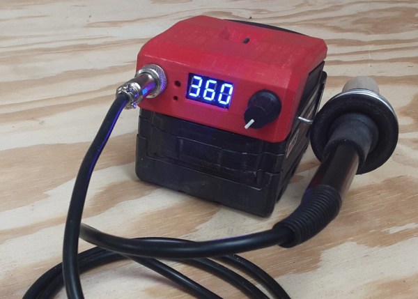
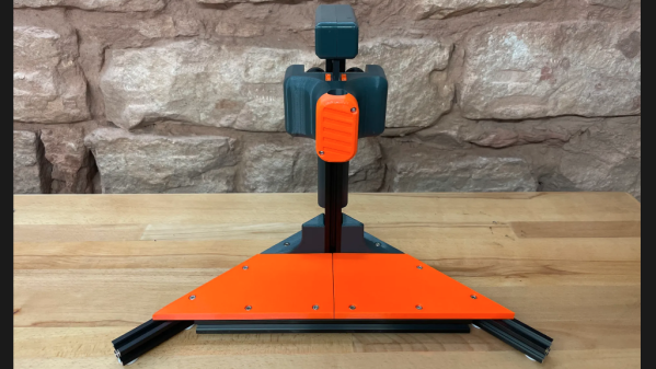
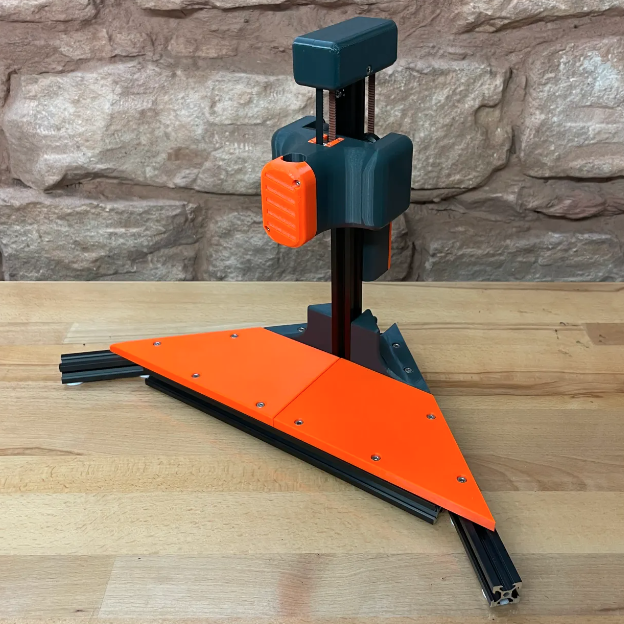
Peer-Reviewed Continuity Tester

One of the core features of the scientific community is the concept of “peer review” where any claims made by a scientist are open to be analyzed and reproduced by others in the community for independent verification. This leads to either rejection of ideas which can’t be reproduced, or strengthening of those ideas when they are. In this community we typically only feature the first step of this process, the original projects from various builders, but we don’t often see someone taking those instructions and “peer reviewing” someone’s build. This is one of those rare cases.

[oxullo] came across [Leo]’s original build for the ultimate continuity tester. This design is much more sensitive than the function which is built in to most multi-meters, and when building this tool specifically some other refinements can be built in as well. [oxullo] began by starting with the original designs, but made several small modifications. Most of these were changing to surface-mount parts, and switching some components for ones already available. Even then, there was still a mistake in the PCB which was eventually corrected. The case for this build is also 3D printed instead of being made out of metal, and with the original video to work from the rest fell into place easily.

[oxullo] is getting comparable results with this continuity tester, so we can officially say that this design is peer reviewed and tested to the highest of standards. If you’re in need of a more sensitive continuity sensor, or just don’t want to shell out for a Fluke meter when you don’t need the rest of its capabilities, this is the way to go. And don’t forget to check out our original write-up for this tester if you missed it the first time around.

Printable One-Way Driver Skips Ratchet For A Clutch

Ratcheting screwdrivers can help you work faster, even if their bulk means they’re not the best option for working in tight spaces. [ukman] decided to build a similar device of his own, relying on a slightly different mechanism — an overrunning clutch.

The design is similar to a freewheel used on a bicycle, allowing free movement in one direction while resisting it in the other. As the screwdriver is turned in one direction, the shaft is wedged by a series of cylinders that lock it in place. However, the geometric shape of the clutch allows the shaft to turn in the other direction without getting wedged in place. The result is a screwdriver that can be turned, rolled back, and turned further. Thus, screws can be tightened without loosening one’s grip on the tool.

With its 3D printed construction, it’s probably not the best tool for heavy-duty, high-torque jobs, but it looks more than capable of handling simple assembly tasks. We’ve seen some other nifty screwdrivers around these parts, too.

Continue reading “Printable One-Way Driver Skips Ratchet For A Clutch”

Angled Drill Guide Helps You With Those Tricky Holes

If you’ve ever tried to drill a hole on an angle with a power drill, you’ve probably drilled some pretty shocking holes. To do it right, you really need some mechanical assistance, and this jig from [Kartik_Nandrui] should do the trick.

The device uses a guide that sits on the surface to be drilled, with a pair of angled connectors that fit two wooden dowels. These connect the guide to a corresponding sleeve that fits around the drill body. The sleeve then slides up and down the dowels, allowing the drill to move in a straight line towards the targeted area.

It’s a useful hack, but we can see room for some improvements that would take it to the next level. Having a way to lock the angle of the guide base would be great for accuracy. As it’s 3D printed, it would also be simple to create a version with a curved guide base that could fit over pipes, or other designs to fit complex geometries like roof sheeting or other corrugated materials.

Sometimes the most interesting hacks are the ones that get us thinking about our own potential projects. If you’ve got any creative tool hacks you’ve been brewing up in the lab, be sure to let us know!

Testing A Laser Cut Wrench VS A Forged Wrench

It is easy to not think much about common tools like screwdrivers and wrenches. But not for [Torque Test Channel]. The channel does a lot of testing of tools and in the video, below, they test a new wrench that is, oddly enough, laser cut instead of forged like the usual wrench.

You would expect a machined wrench to be weaker than a forged wrench. We were impressed, though, that there is so much difference between wrenches when you start making measurements.

Speaking of measurements, we would like to see more details of the test setups shown both in the video and in some of the video clips included. We did enjoy seeing the examination of the internal grain structure of both wrenches.

Be forewarned. Watching this video is likely going to send you to the computer to buy some new wrenches, especially if you don’t have 30/60 head wrenches.

The real question is why laser cut a wrench? It doesn’t seem like it is actually better than the forged variant. It is more expensive, but the setup costs for forging are higher. Particularly for a tool made in the United States, forging is both expensive and it is difficult to find time on the limited number of large-scale forges left in the country.

Continue reading “Testing A Laser Cut Wrench VS A Forged Wrench”

Resulting tweezer assembly, with a 3D printed replacement case for both of the probes

Hackaday Prize 2022: Glue-Hindered Smart Tweezer Repair Involves A Rebuild

[Dan Julio] owns a pair of Miniware multimeter tweezers, a nifty helper tool for all things SMD exploration. One day, he found them broken – unable to recognize any component between the two probes. He thought it could be a broken connection problem, and decided to take them apart. Presence of some screws on their case fooled him – in the end, it turned out that the case was glued together, and could only be opened destructively. For an entry in the “Reuse, Recycle, Revamp” round of 2022 Hackaday Prize, he tells us how he brought these tweezers back from the dead.

During the disassembly, he broke a custom flexible PCB, which wasn’t reassuring either. However, that was no reason to give up – he reverse-engineered the connections and the charging circuitry, then assembled parts of the broken tweezers together using a small generic protoboard as a base. Indeed, it was likely a broken connection between probes, because the reassembled tweezers worked!

Of course, having exposed PCBs wouldn’t do, and from the very start, assembling these tweezers back together was not an option. Instead, he developed a replacement case in OpenSCAD, bringing the tweezers back to life as his trusty tool – and still leaving repairability on the table. If you’re interested in the details, he goes more into how these tweezers are designed when it comes to charging and connectivity, and we recommend that you give his write-up a read!

We’ve been seeing smart tweezers around for over a decade now, from reviews and hacks of commercially made ones, to DIY chopstick-based and PCB-based ones. If you already own a pair of tweezers you’ve grown attached to, you can neatly retrofit them with a capacitance sensing function!

Flexible Grip For Hammer Made With 3D Printing Pen

When it comes to putting a flexible grip on a tool, you might reach for a self-fusing silicone tape or other similar product. However, [Potent Printables] has discovered you can easily create a flexible grip using a 3D-printing pen and some flex filament.

In this case, a hammer first gets a layer of blue painters tape wrapped around its wooden handle. This serves as a base layer to promote good adhesion. A simple paper template was then printed as a guide for creating the graphics on the flexible grip. Flexible filament was fed through the 3D pen, with the red and black details of the graphics printed first. Then, white flex filament was used to make the rest of the flexible grip. A wood burning tool was then used to smooth out the first layer of flex filament, before a second layer was added on top.

The result is a flexible white grip on the hammer which is stuck fast, likely due to shrinkage as the plastic cooled after printing. We’ve seen some other creative grips made with 3D printing before, too. Video after the break.

Continue reading “Flexible Grip For Hammer Made With 3D Printing Pen”

SMT Part Counter Aims To Ease Taking Inventory

[Nick Poole] has an interesting idea for a new tool, one that has the simple goal of making accurate part counts of SMT reels as easy as pulling tape through a device. That device is the BeanCounter, an upcoming small handheld unit of his own design that counts parts as quickly as one can pull tape through a slot. The device is powered by a CR2032 cell and and works with 8 mm wide tapes up to 2 mm in height, which [Nick] says covers most 0805 or smaller sized parts, as well as things like SOT-23 transistors.

Why would one want to make such a task easier? Two compelling reasons for such a tool include: taking inventory of parts on partial reels or cut tape, and creating segments that contain a known number of parts.

The first is handy for obvious reasons, and the second is useful for things like creating kits. In fact, the usefulness of this tool for creating tape segments of fixed length is perhaps not obvious to anyone who hasn’t done it by hand. Sure, one can measure SMT tape with a ruler or a reference mark to yield a segment containing a fixed number of parts, but that involves a lot of handling and doesn’t scale up very well. In fact, the hassle of cutting tape segments accurately and repeatedly is a common pain point, so making the job easier has value.

If you looked at the photos and suspected that the big, 7-segment numeric display is done with clever PCB fabrication options (making segments by shining LEDs through PCB layers, a trick we always like to see) you’re not alone. After all, [Nick] has a lot of experience in getting clever with board fabrication, and eagle-eyed readers may even suspect that the reset and setup buttons on the edge of the tool are created by using flex PCB segments as switches. Want the nitty-gritty details? Visit the GitHub repository for the project and see it all for yourself at the CAD level.