Flexible Grip For Hammer Made With 3D Printing Pen

When it comes to putting a flexible grip on a tool, you might reach for a self-fusing silicone tape or other similar product. However, [Potent Printables] has discovered you can easily create a flexible grip using a 3D-printing pen and some flex filament.

In this case, a hammer first gets a layer of blue painters tape wrapped around its wooden handle. This serves as a base layer to promote good adhesion. A simple paper template was then printed as a guide for creating the graphics on the flexible grip. Flexible filament was fed through the 3D pen, with the red and black details of the graphics printed first. Then, white flex filament was used to make the rest of the flexible grip. A wood burning tool was then used to smooth out the first layer of flex filament, before a second layer was added on top.

The result is a flexible white grip on the hammer which is stuck fast, likely due to shrinkage as the plastic cooled after printing. We’ve seen some other creative grips made with 3D printing before, too. Video after the break.

Continue reading “Flexible Grip For Hammer Made With 3D Printing Pen”

SMT Part Counter Aims To Ease Taking Inventory

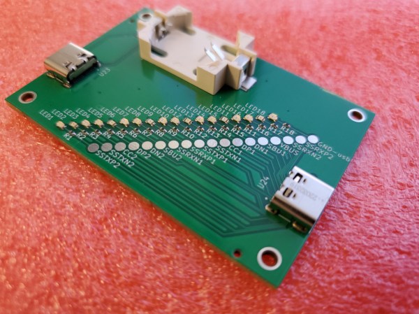
[Nick Poole] has an interesting idea for a new tool, one that has the simple goal of making accurate part counts of SMT reels as easy as pulling tape through a device. That device is the BeanCounter, an upcoming small handheld unit of his own design that counts parts as quickly as one can pull tape through a slot. The device is powered by a CR2032 cell and and works with 8 mm wide tapes up to 2 mm in height, which [Nick] says covers most 0805 or smaller sized parts, as well as things like SOT-23 transistors.

Why would one want to make such a task easier? Two compelling reasons for such a tool include: taking inventory of parts on partial reels or cut tape, and creating segments that contain a known number of parts.

The first is handy for obvious reasons, and the second is useful for things like creating kits. In fact, the usefulness of this tool for creating tape segments of fixed length is perhaps not obvious to anyone who hasn’t done it by hand. Sure, one can measure SMT tape with a ruler or a reference mark to yield a segment containing a fixed number of parts, but that involves a lot of handling and doesn’t scale up very well. In fact, the hassle of cutting tape segments accurately and repeatedly is a common pain point, so making the job easier has value.

If you looked at the photos and suspected that the big, 7-segment numeric display is done with clever PCB fabrication options (making segments by shining LEDs through PCB layers, a trick we always like to see) you’re not alone. After all, [Nick] has a lot of experience in getting clever with board fabrication, and eagle-eyed readers may even suspect that the reset and setup buttons on the edge of the tool are created by using flex PCB segments as switches. Want the nitty-gritty details? Visit the GitHub repository for the project and see it all for yourself at the CAD level.

Confessions Of A Crimpoholic

Hi, my name is Dan and I’m a crimpoholic.

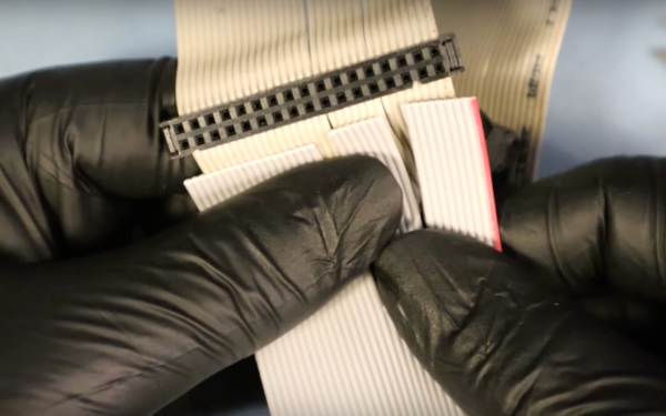
Honestly, I didn’t know I was a serial abuser of crimping tools until this weekend. I’ve been working on a small solar power system, and on Saturday I found myself struggling to get the BMS installed on the battery. I bought a Bluetooth dongle to connect the BMS to a smartphone app for checking the individual cells of the battery. I assumed it would just plug right into the UART port on the BMS, but alas — different connectors. So off I went to my bench, looking for a sensible way to make the connection.

My first thought was to simply log the connector off the dongle and solder the leads to the traces on the PCB right below the UART port. But then I saw that the pins in the port looked like 0.1″ pitch, so I rummaged through my stash to see what I could find. To my surprise, I had not only a kit of 0.1″ female crimps and housings, but I also had the crimping tool for them! I had no memory of making the purchase, but I thanked my lucky stars that I did, and got on with the job.

Continue reading “Confessions Of A Crimpoholic”

Keep The Sparks Away With A Plasma Cutting Table

For one-off projects or prototypes it’s not uncommon for us to make do with whatever workspace we have on hand. Using a deck railing as an impromptu sawhorse, for example, is one that might be familiar to anyone who owns a circular saw, but [Daniel] has a slightly different situation. He had been setting up metal workpieces on random chunks of brick in order to use his plasma cutter, but just like the home handyman who gets tired of nicking their deck with a saw, he decided to come up with a more permanent solution and built a custom plasma cutting table.

Plasma cutting has a tendency to throw up a lot of sparks, so most commercial offerings for plasma cutting tables include a water bath to catch all of the debris from the cutting process. [Daniel] builds his table over a metal tub to hold some water for this purpose. The table itself is built out of aluminum and designed to be built without welding even though most people with plasma cutters probably have welders as well. The frame is designed to be exceptionally strong and includes curved slats which add to the strength of the table. The table is also designed to be portable, so the curved slats stay in place when the table is moved.

While this might seem like an average metal table at first glance, the table is actually being designed with a homemade CNC machine in mind which [Daniel] is working on. The CNC plasma cutter needs a sturdy, flat surface and can’t be set up on bricks in the driveway, so this table suits both [Daniel]’s immediate needs to not shower himself in sparks every time he cuts something and also his future CNC machine’s need for a sturdy, flat workspace. We look forward to seeing that build being completed but in the meantime take a look at this motorized plasma cutter which has the beginnings of a CNC machine if in one direction only.

Continue reading “Keep The Sparks Away With A Plasma Cutting Table”

Mini-lathe carriage wheel

Improving A Mini-Lathe With A Few Clever Hacks

Like many budget machinists, the delightfully optimistically named [We Can Do That Better] had trouble with some of the finer controls on his import mini-lathe. But rather than suffer through it, he chose to rectify the machine’s shortcomings and in the process, teach everyone a bunch of great tips.

[We Can Do That Better]’s lathe retrofit focused on the carriage handwheel, which appears to lack proper bearings and wobbles around in a most imprecise manner. On top of that, the gearing of the drive made for an unsatisfying 19 mm of carriage travel per revolution of the handwheel. A single gear change made that an even 20 mm per rev, which when coupled with a calibrated and indexed handwheel ring greatly simplifies carriage travel measurements.

While the end result of the build is pretty great in its own right, for our money the best part of the video is its rich collection of machinist’s tips. The use of a wooden dowel and a printed paper template to stand in for a proper dividing head was brilliant, as was using the tailstock of the lathe to drive an engraving tool to cut the index lines. We’ve seen the use of a Dremel tool mounted to the toolpost to stand in for a milling machine before, but it’s always nice to see that trick used. And the mechanism for locking the dial to the handwheel was really clever, too.

Considering a mini-lathe? As encouraging as [We Can Do That Better]’s experience may be, it might be wise to take a deep dive into the pros and cons of such a machine.

Continue reading “Improving A Mini-Lathe With A Few Clever Hacks”

Vise Tripod Lets You Put The Tool Where You Need It

Vises are useful things for holding whatever you’re working on, but too often they’re stuck to a bench. [seamster] has experienced the glory of having a more portable solution, however, and has shared his design for a heavy duty vise tripod that provides just that.

The trick is that to be useful, the design must be heavy and stout enough to hold the vise without tipping over. For this build, [seamster] selected a fat steel pipe with 1/4″ thick walls, some solid bars and some 3/8″ thick plate. Legs and arms where then fabbed up from the bar material and welded up to form the tripod. A stout plate for the vise was then welded on top of the pipe, and the vise mounted pride of place on top.

It’s not a particularly difficult build, but it’s a smart idea that gets you a vise you can easily drag to where it’s needed. If you don’t have the vise itself, consider this hydraulic build. Meanwhile, if you’ve been whipping up your own useful workshop hacks, let us know!

Handheld Bandsaw Gets Standup Conversion With Scrap Lumber

Handheld band saws exist, and can be highly useful tools. However, they lack some of the finesse and precision of the more traditional upright units, particularly for with smaller workpieces. [Honus] set about rectifying this, building a stand for their DeWalt handheld bandsaw out of scrap lumber.

The stand consists of some hefty wooden beams sawn to length and screwed together to make a support for the bandsaw. A nice 1/4″ thick aluminium plate is installed as a baseplate for cutting.

Then, the handheld bandsaw itself is attached to the rig, held in place with a bolt and a large zip tie. The zip tie is fastened around the trigger, holding it down all the time. Then, a switched powerboard is used to turn the saw on and off as needed. Importantly, simply cutting a ziptie and removing a bolt is enough to restore the handheld saw to its original purpose.

It’s a tidy build and one that makes an existing tool more useful for minimal extra cost. We’ve actually seen bandsaws built from scratch, too. If you’re cooking up your own great hacks in the home shop, be sure to let us know!