The hobbyists of the early days of the home computer era worked wonders with the comparatively primitive chips of the day, and what couldn’t be accomplished with a Z80 or a 6502 was often relegated to complex designs based on logic chips and discrete components. One wonders what these hackers could have accomplished with the modern components we take for granted.
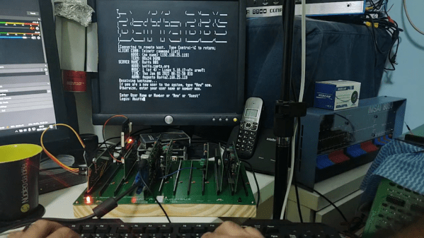
Perhaps it would be something like this minimal serial terminal for the current crop of homebrew retrocomputers. The board is by [Augusto Baffa] and is used in his Baffa-2 homebrew microcomputer, an RC2014-esque Z80 machine that runs CP/M. This terminal board is one of many peripheral boards that plug into the Baffa-2’s backplane, but it’s one of the few that seems to have taken the shortcut of using modern microcontrollers to get its job done. The board sports a pair of ATmega328s; one handles serial communication with the Baffa-2 backplane, while the other takes care of running the VGA interface. The card also has a PS/2 keyboard interface, and supports VT-100 ANSI escapes. The video below shows it in action with a 17″ LCD monitor in the old 4:3 aspect ratio.
We like the way this terminal card gets the job done simply and easily, and we really like the look of the Baffa-2 itself. We also spied an IMSAI 8080 and an Altair 8800 in the background of the video. We’d love to know more about those.
Continue reading “Retro Serial Terminal Uses Modern Chips To Get CP/M Machine Talking”