Only about 10% of blind people around the world can read Braille. One primary reason is the high cost of Braille displays. The cost is a result of their complexity and reliability – required to ensure that they are able to handle wear and tear.
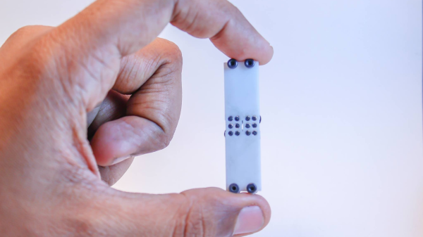
[Vijay] has been working since 3 years on a Refreshable Braille Display but has only recently been able to make some substantial progress after teaming up with [Paul D’souza]. During his initial experiments, he used dot matrix printer heads, but the current version uses tiny vibration motors as used in mobile phones. He’s converting rotary motion of the tiny motors in to linear movement for pushing the Braille “cell” pins up and down. The eccentric weight on the vibration motor is replaced with a shaped cam. Continuous rotation of the cam is limited by a stopper, which is part of the 3D printed housing that holds the motors. Another 3D printed part has three cam followers, levers, springs and Braille pins rolled in one piece, to create half a Braille cell. Depending on the cam position, the pins are either pushed up or down. One Braille cell module consists of two cam follower pieces, a housing for six vibration motors, and a cover plate. Multiple modules are chained together to form the display.
The next step would be to work on the electronics – in particular ensuring that he is able to control the motor movement in both directions in a controlled manner. Chime in with your comments if you have any ideas. The 3D design files are available from his Dropbox folder.
Continue reading “Refreshable Braille Display And Braille Keyboard”


 This project is